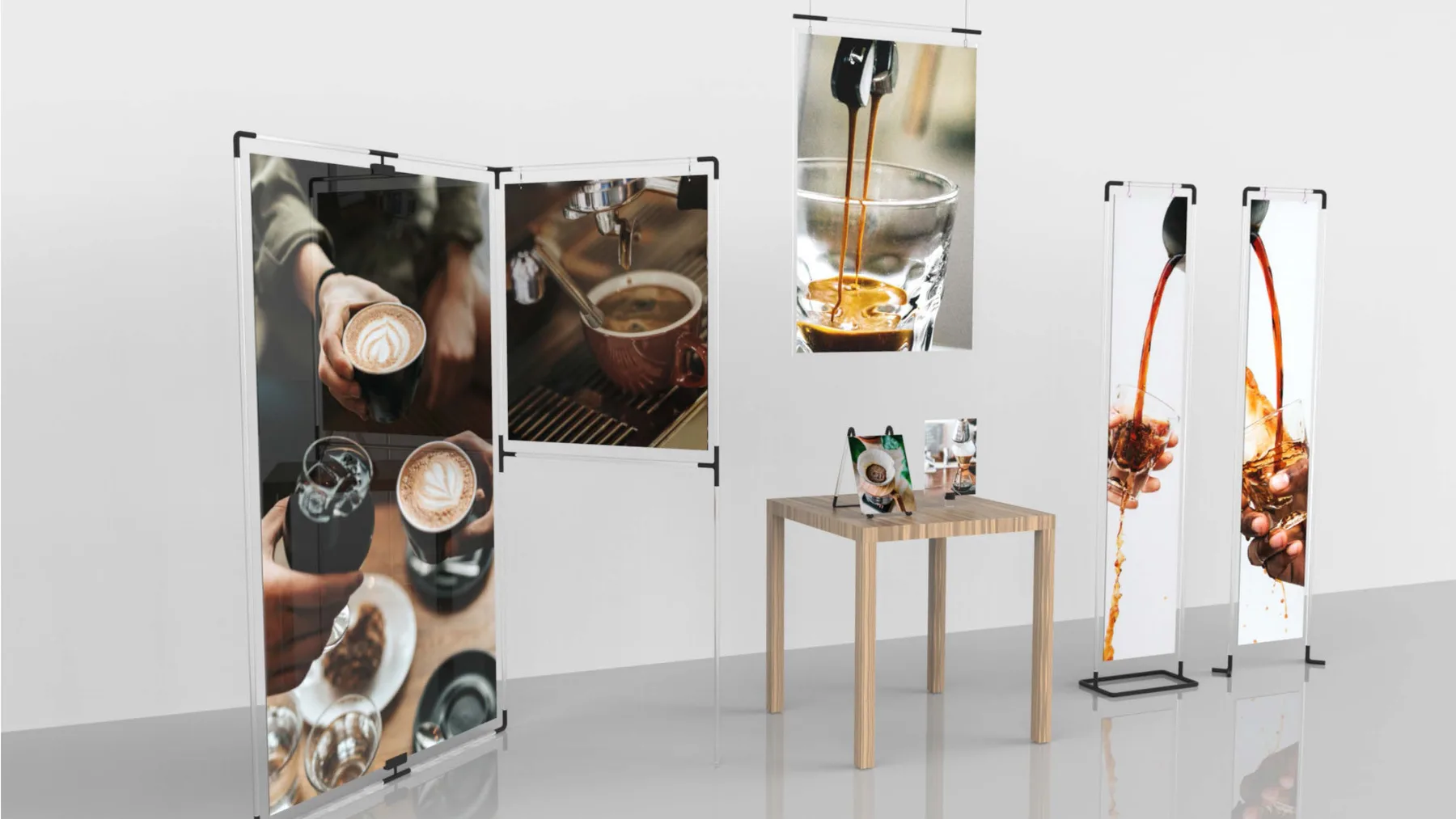
← Selected work Case study / Industrial Designer

Industrial Design

Studio D / VGS

I explored three ways a retail display could change size, placement, and purpose without starting over each time.

  • Industrial Design
  • Retail
Studio D / VGS
Role

Industrial Designer

Deliverables

Research · Display concepts · Connection studies · 3D renderings

The assignment

One system should be able to take more than one shape.

At Studio D, I developed three directions for a modular retail display system for VGS. The work tested how a common set of parts could support graphics and merchandise in different spaces without demanding a new display for every use.
Collage of modular retail display concepts for Studio D and VGS
The study in one view
01 / Understand the need02 / Test three systems03 / Identify the next steps
01

The brief

Define the problem

The brief was not simply to make a display look newer. VGS needed a system that could change with the space, the merchandise, and the campaign while remaining practical to make and use.
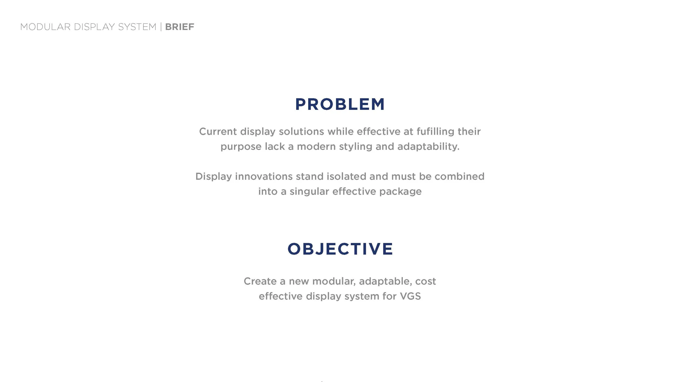
The brief and objective in the Structure VGS concept presentation
02The brief and objective
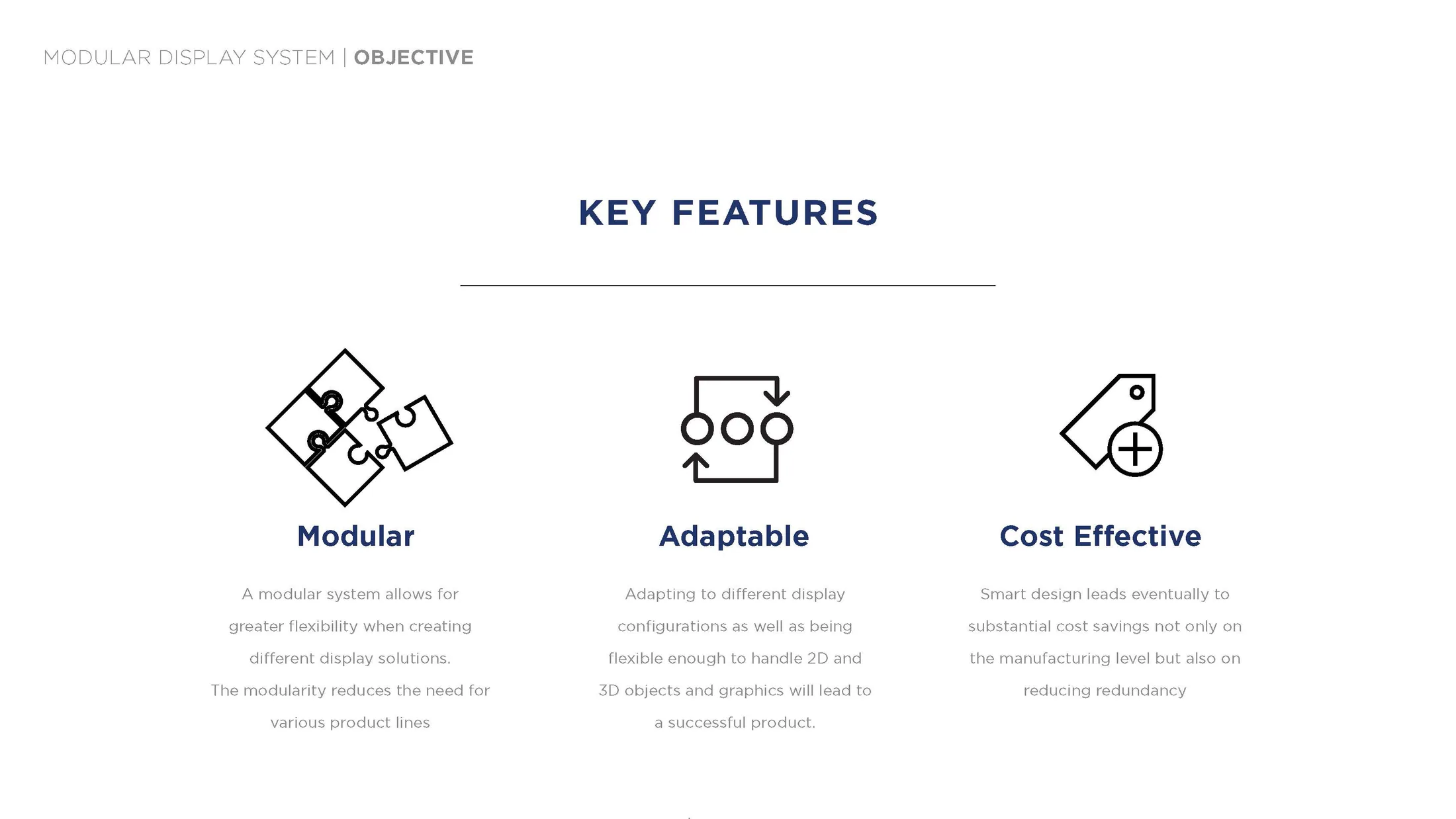
The three measures of success in the Structure VGS concept presentation
03The three measures of success
02

Research and direction

Look beyond a single display

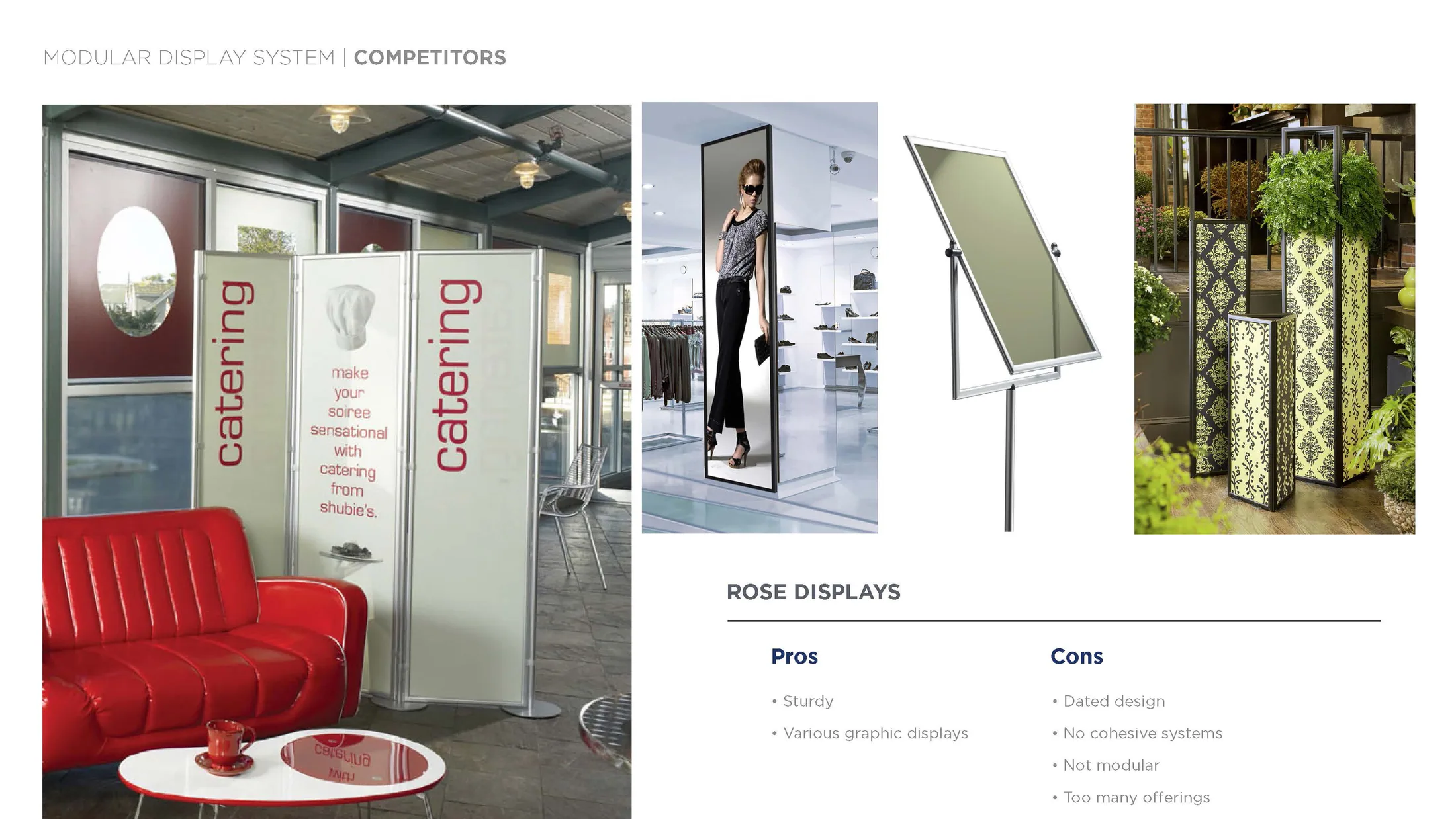
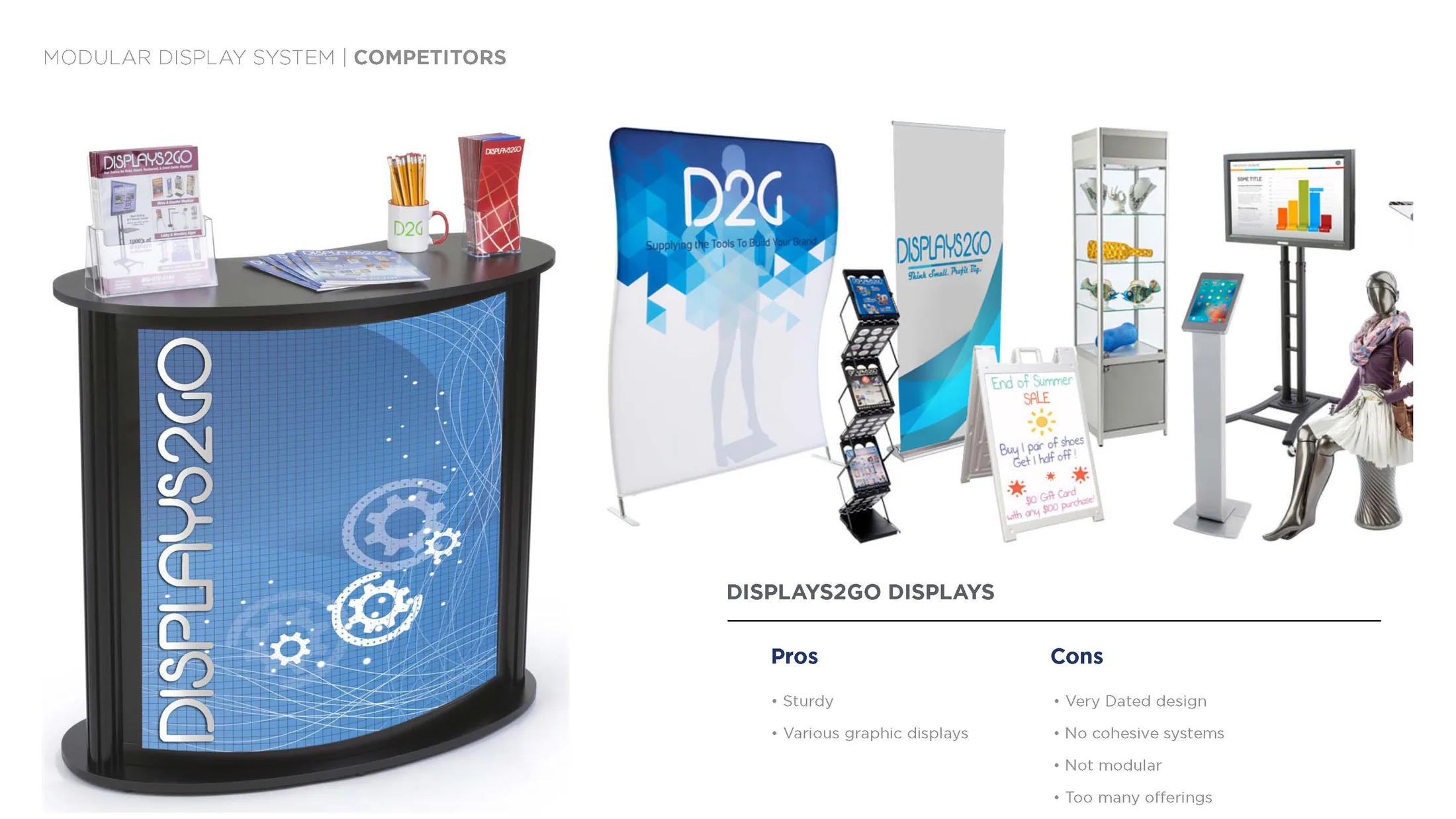
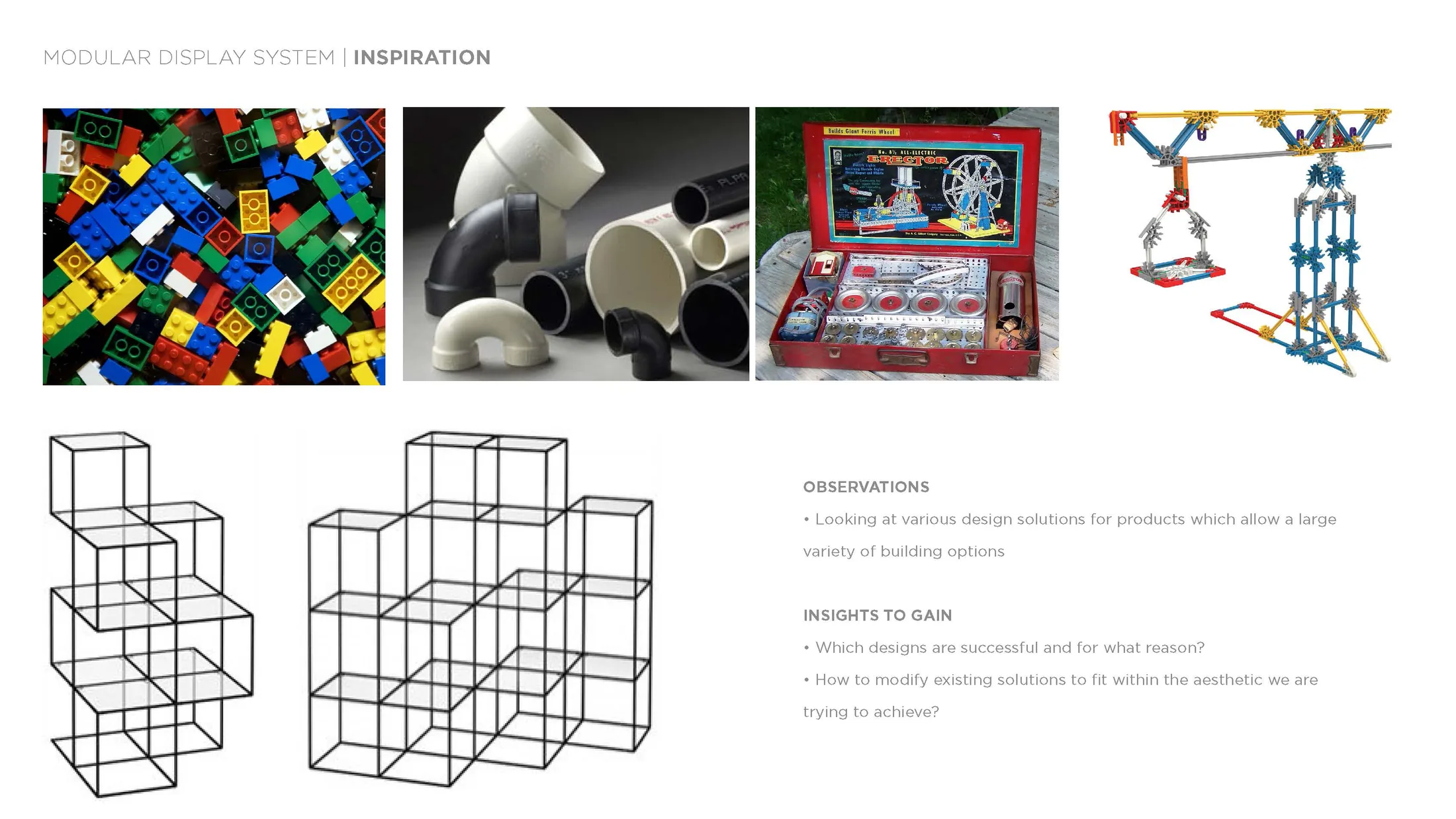
I reviewed existing retail systems, then pulled out the details that could make a modular structure useful in several settings. Placement, graphics, scale, and assembly all had to be considered before choosing a form.
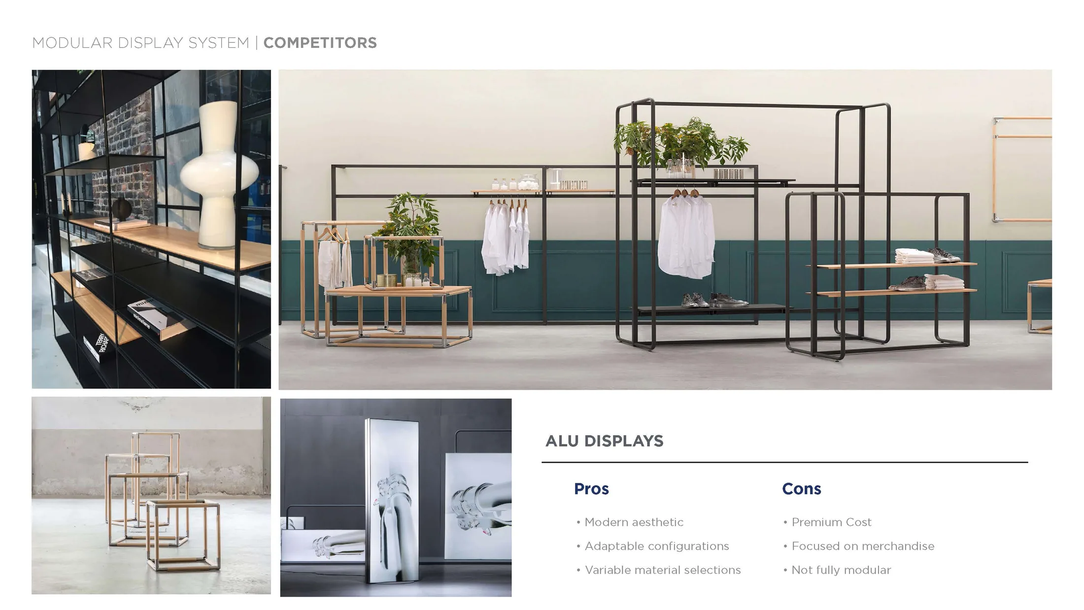
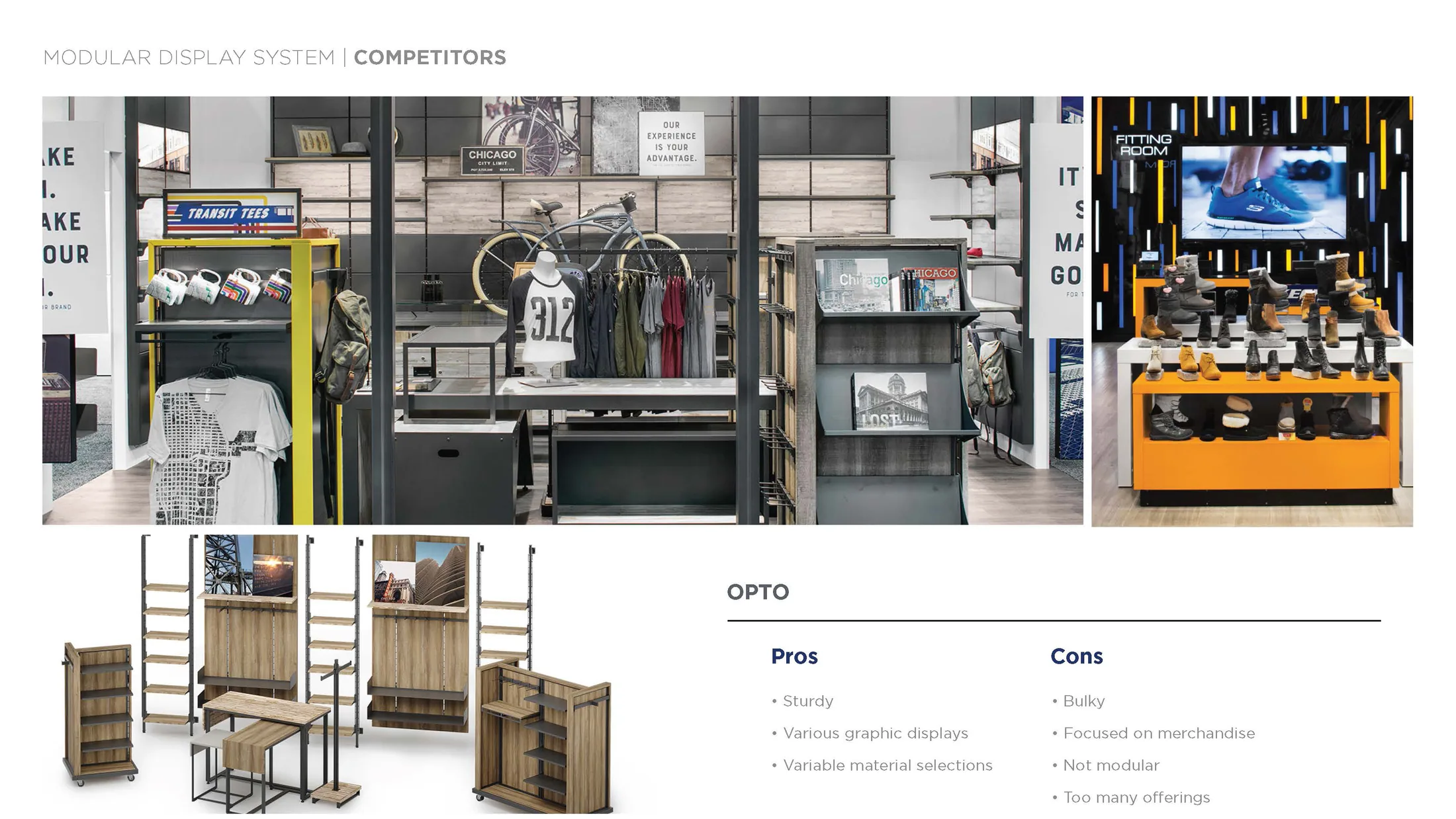
Competitor display review in the Structure VGS concept presentation
05Competitor display review
How existing systems present product in the Structure VGS concept presentation
06How existing systems present product
Structural approaches in the market in the Structure VGS concept presentation
07Structural approaches in the market
What the comparison revealed in the Structure VGS concept presentation
08What the comparison revealed
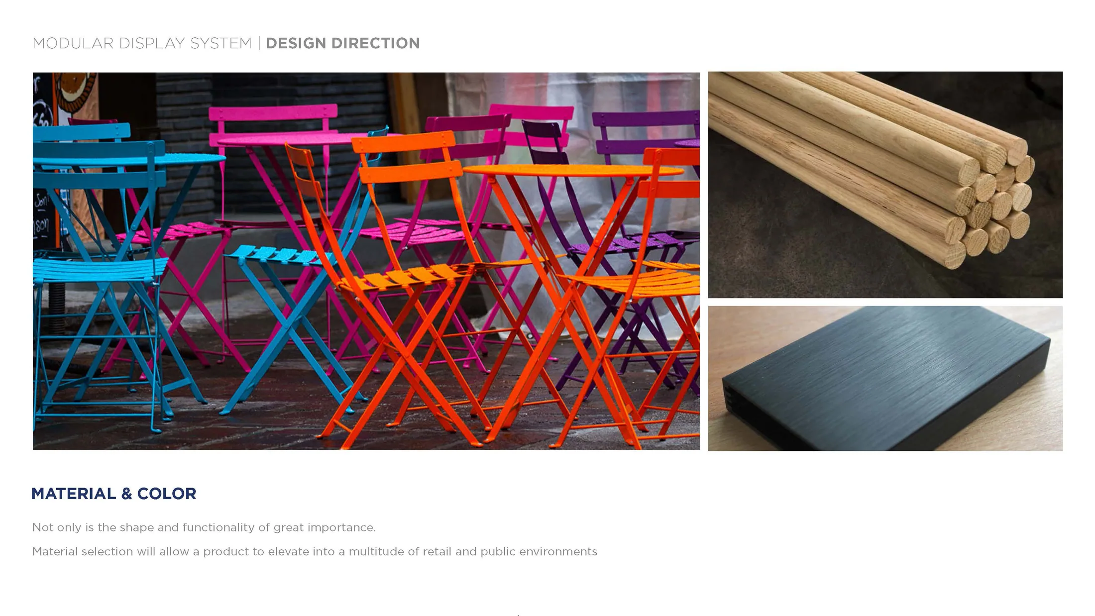
Display and material references in the Structure VGS concept presentation
10Display and material references
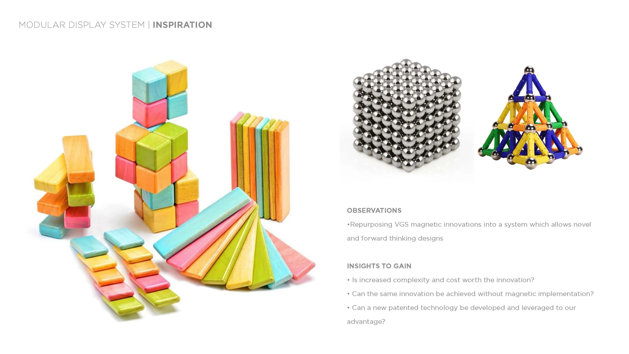
Further visual references in the Structure VGS concept presentation
11Further visual references
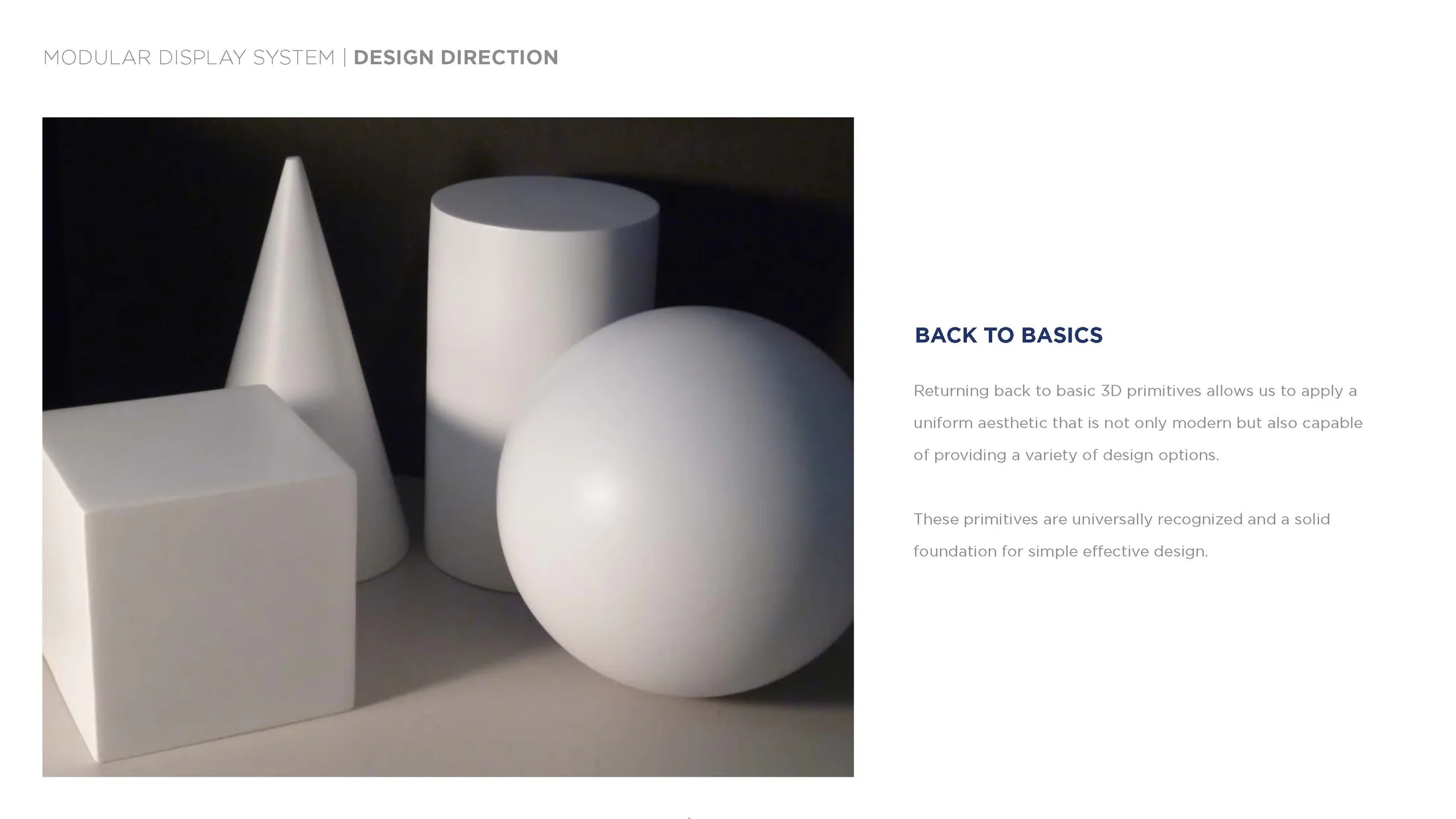
Early design direction in the Structure VGS concept presentation
13Early design direction
Ways the structure might be placed in the Structure VGS concept presentation
14Ways the structure might be placed
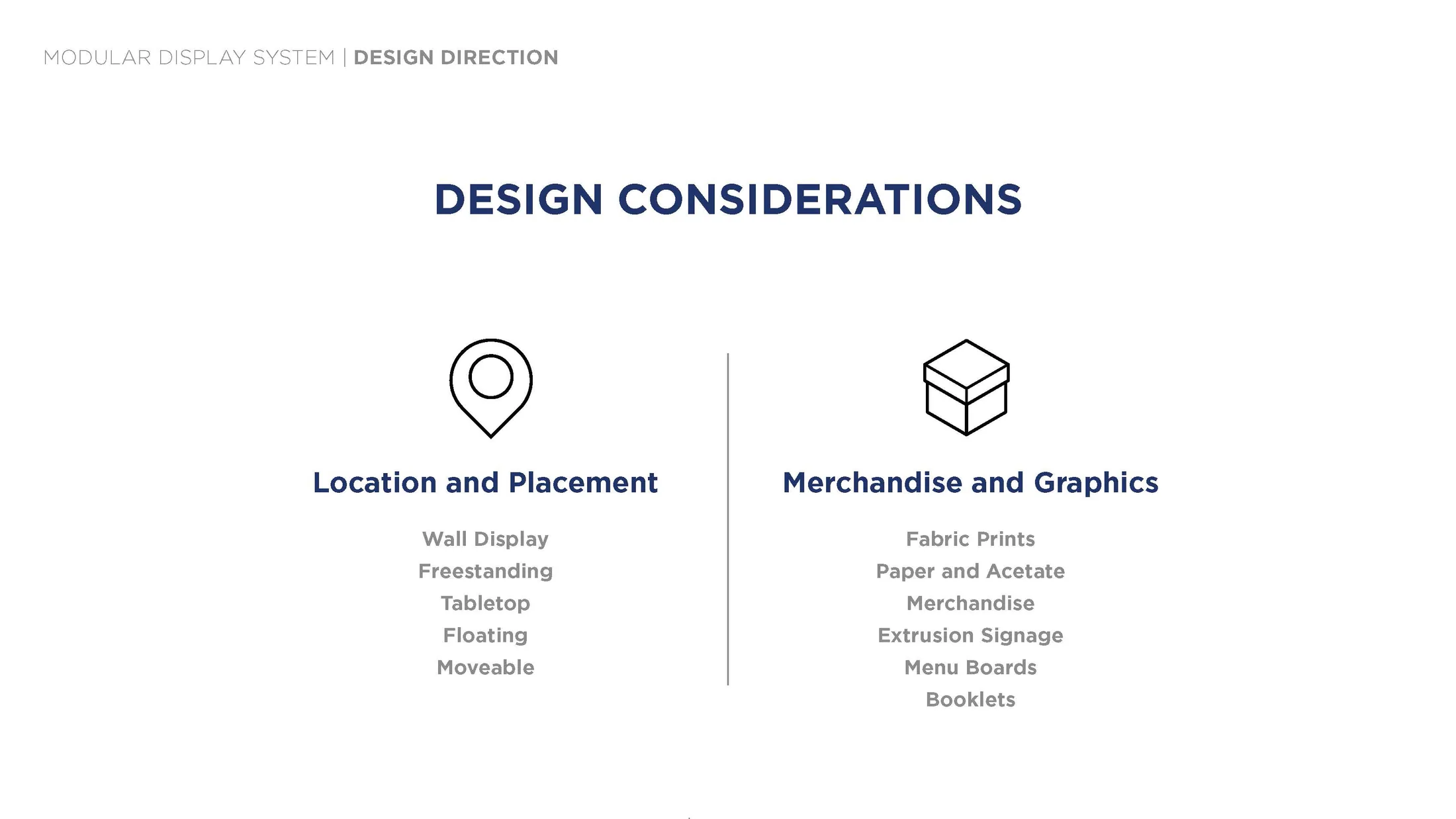
Considering graphics and merchandise in the Structure VGS concept presentation
15Considering graphics and merchandise
03

Option one

Build around a single node

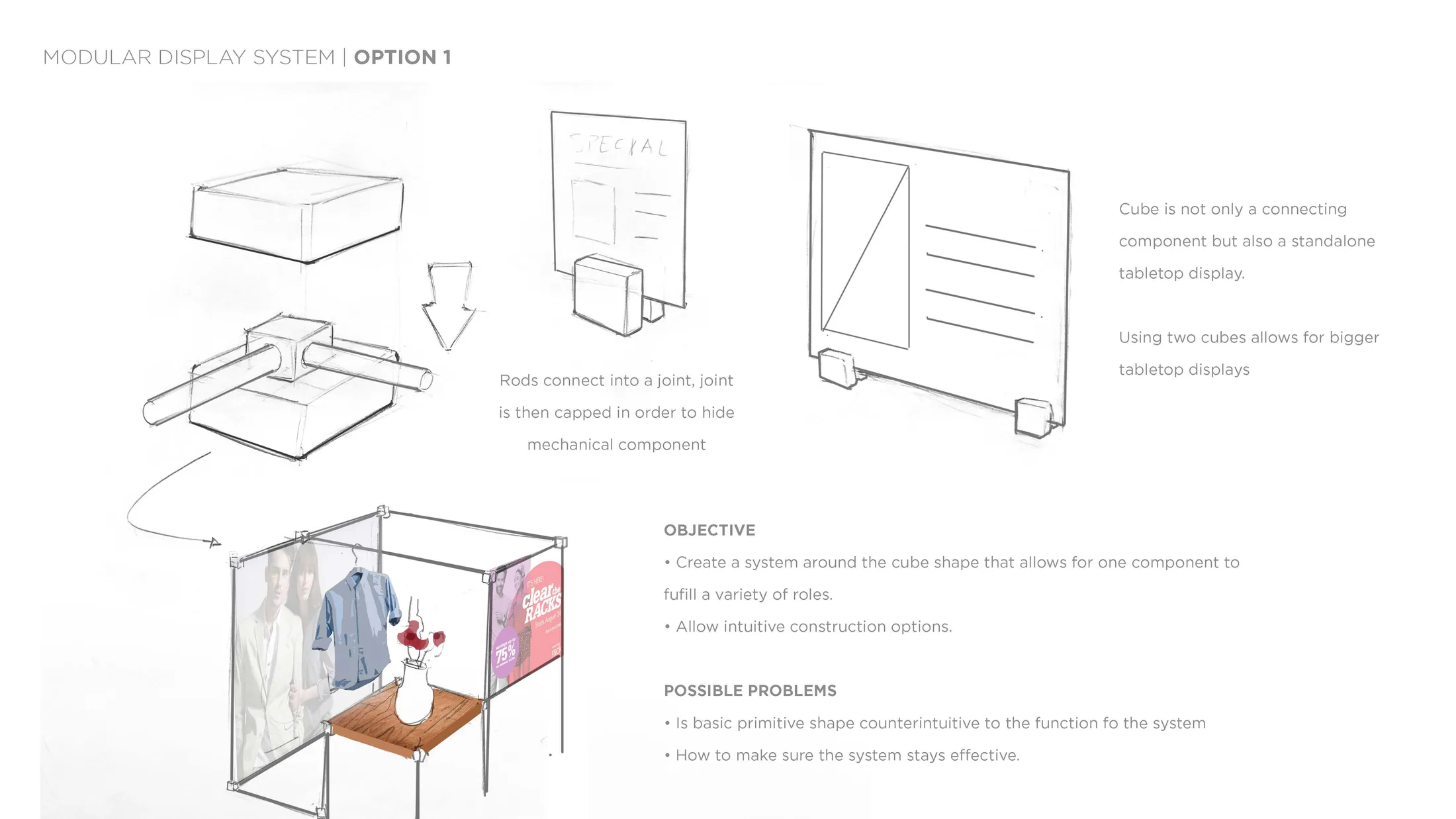
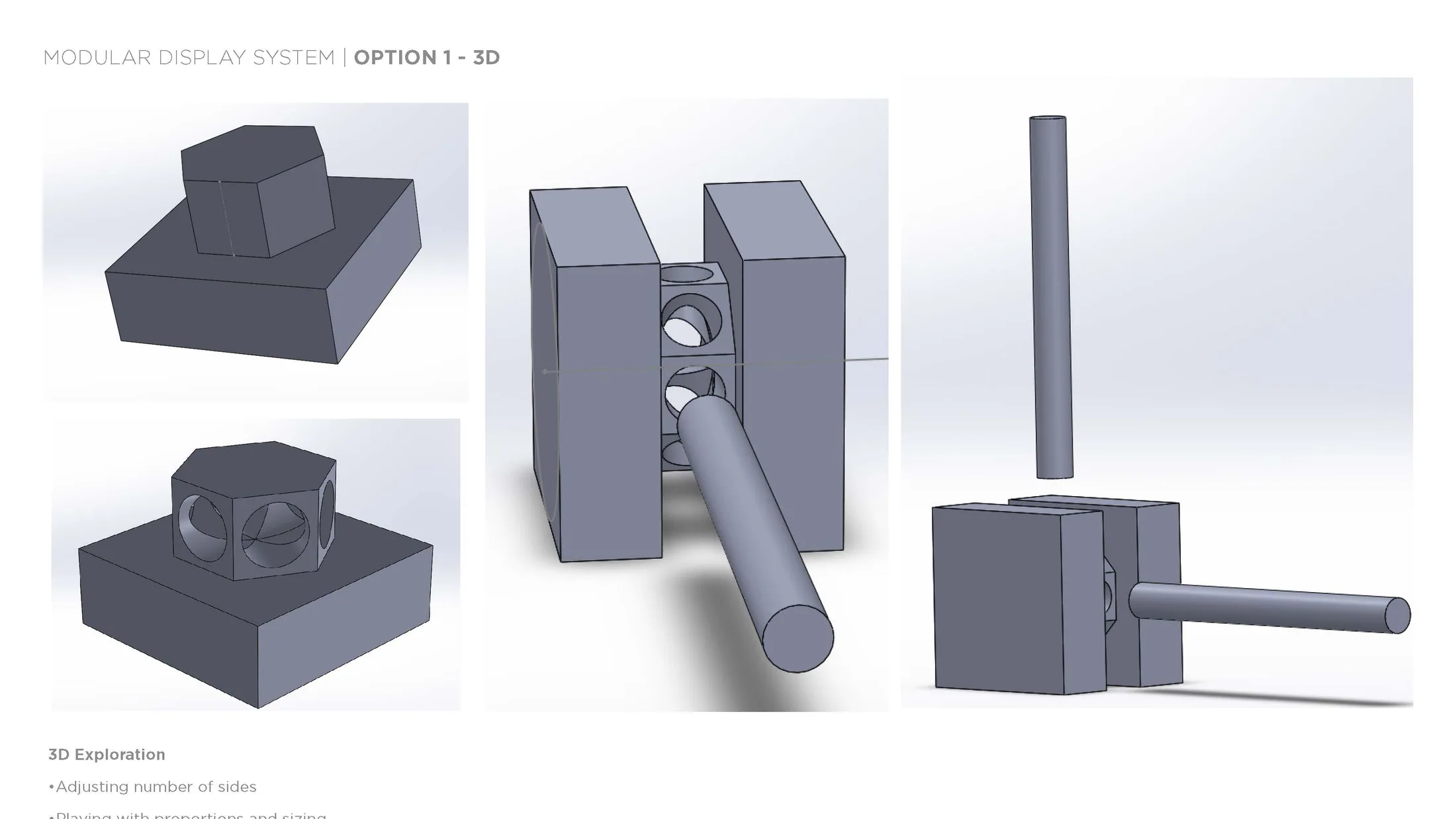
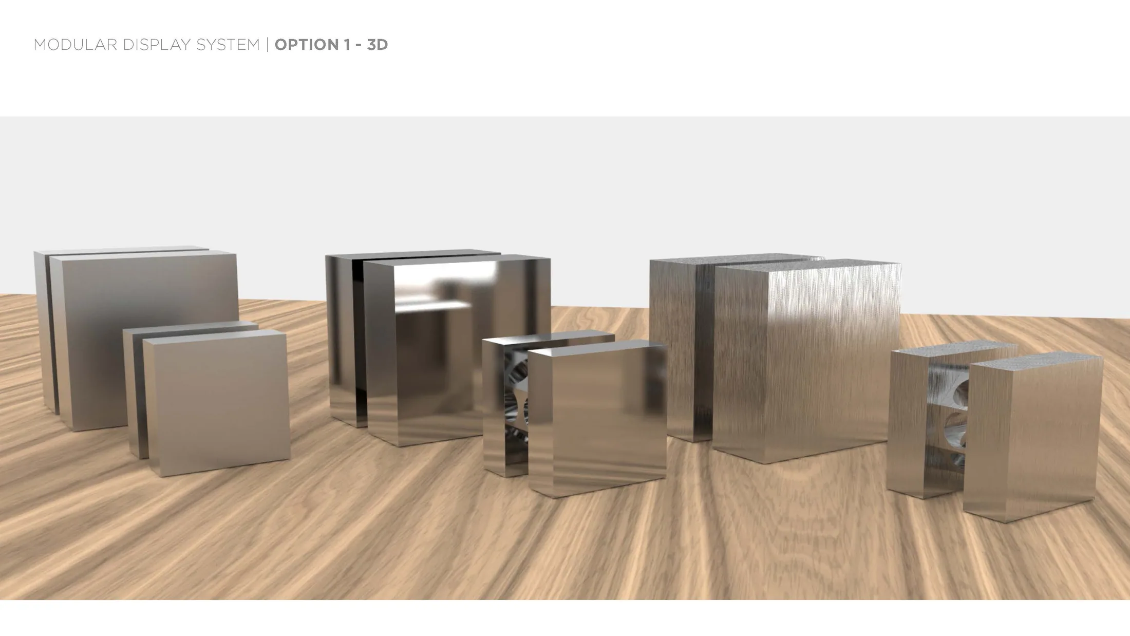
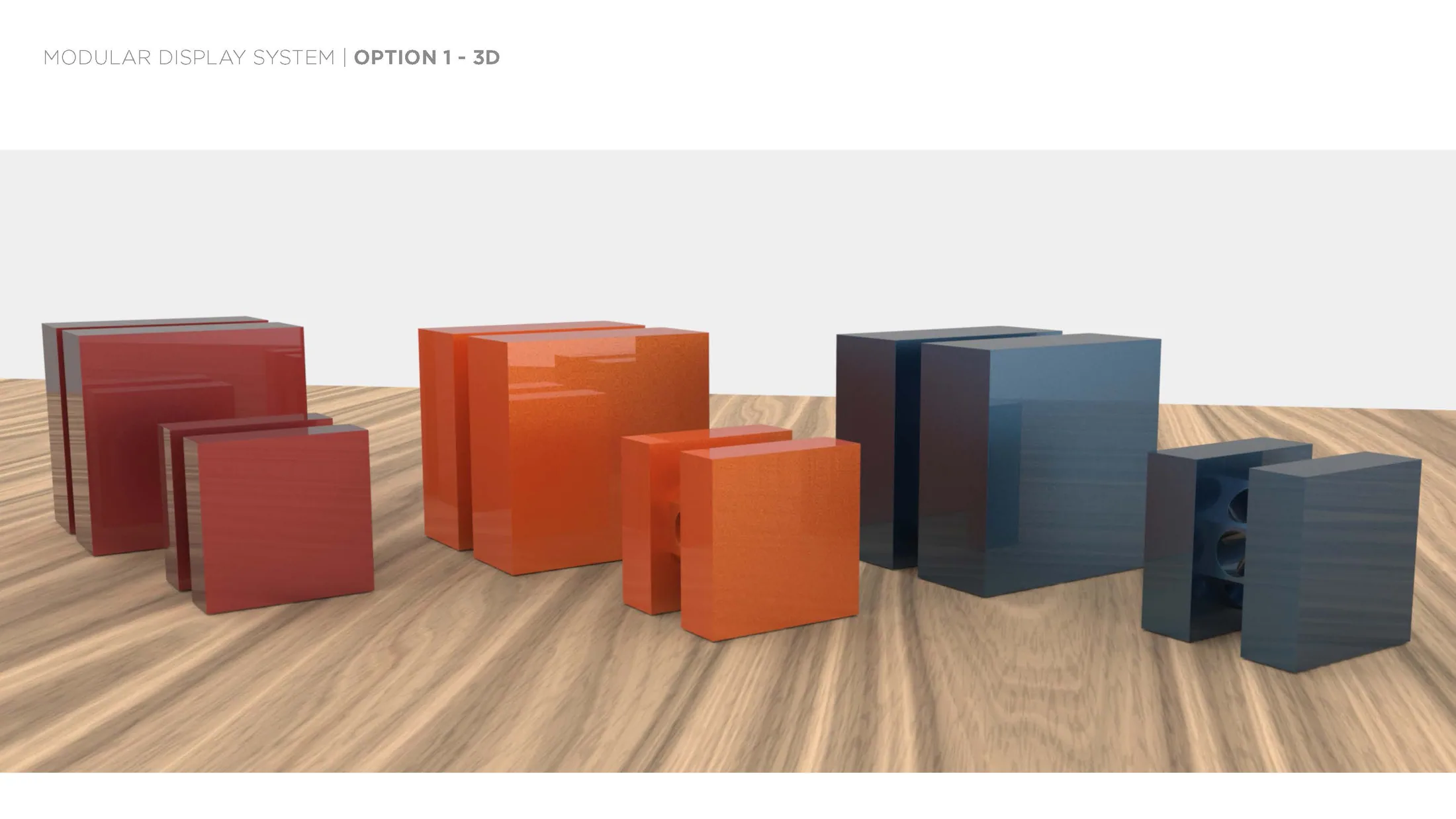
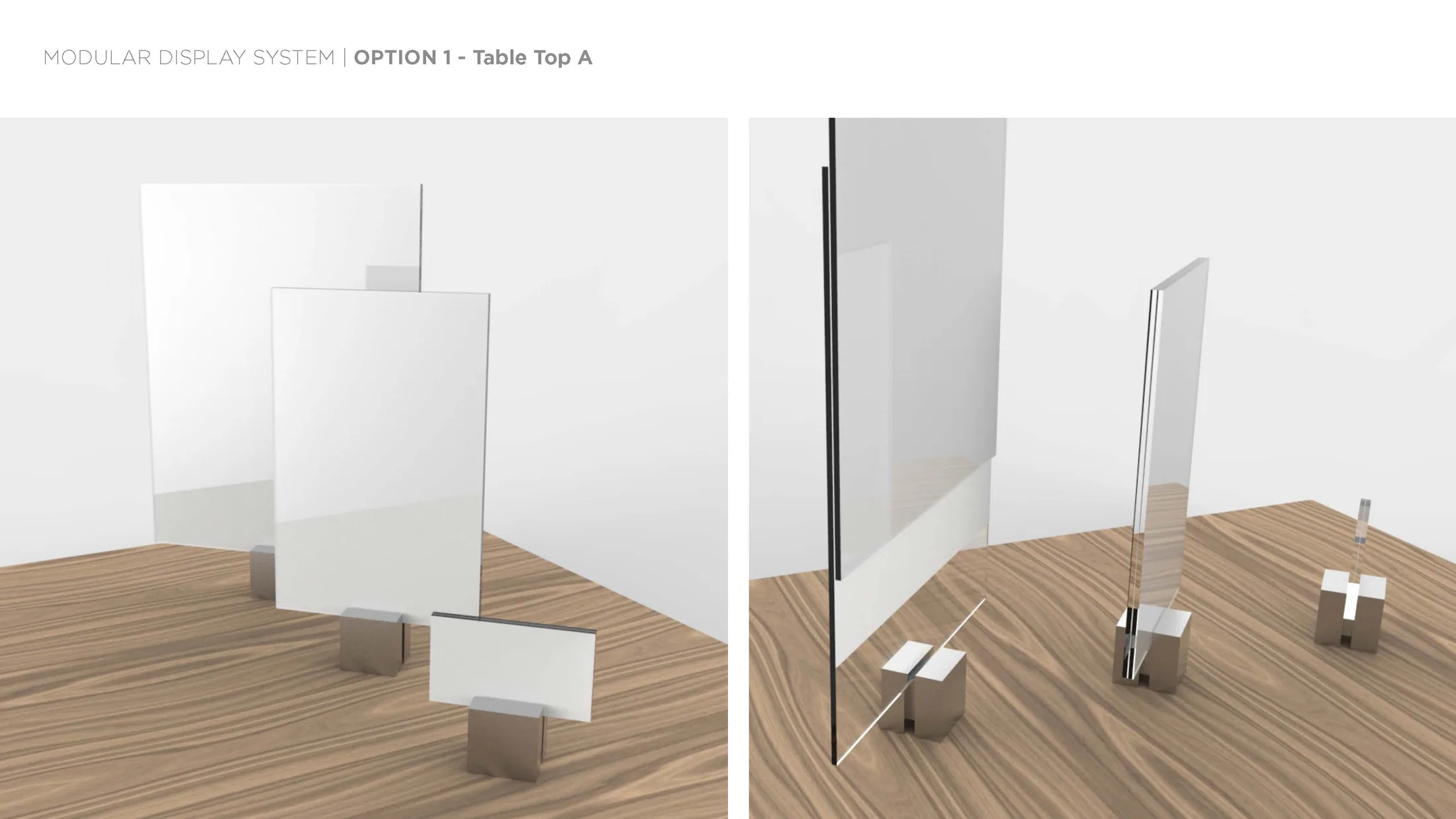
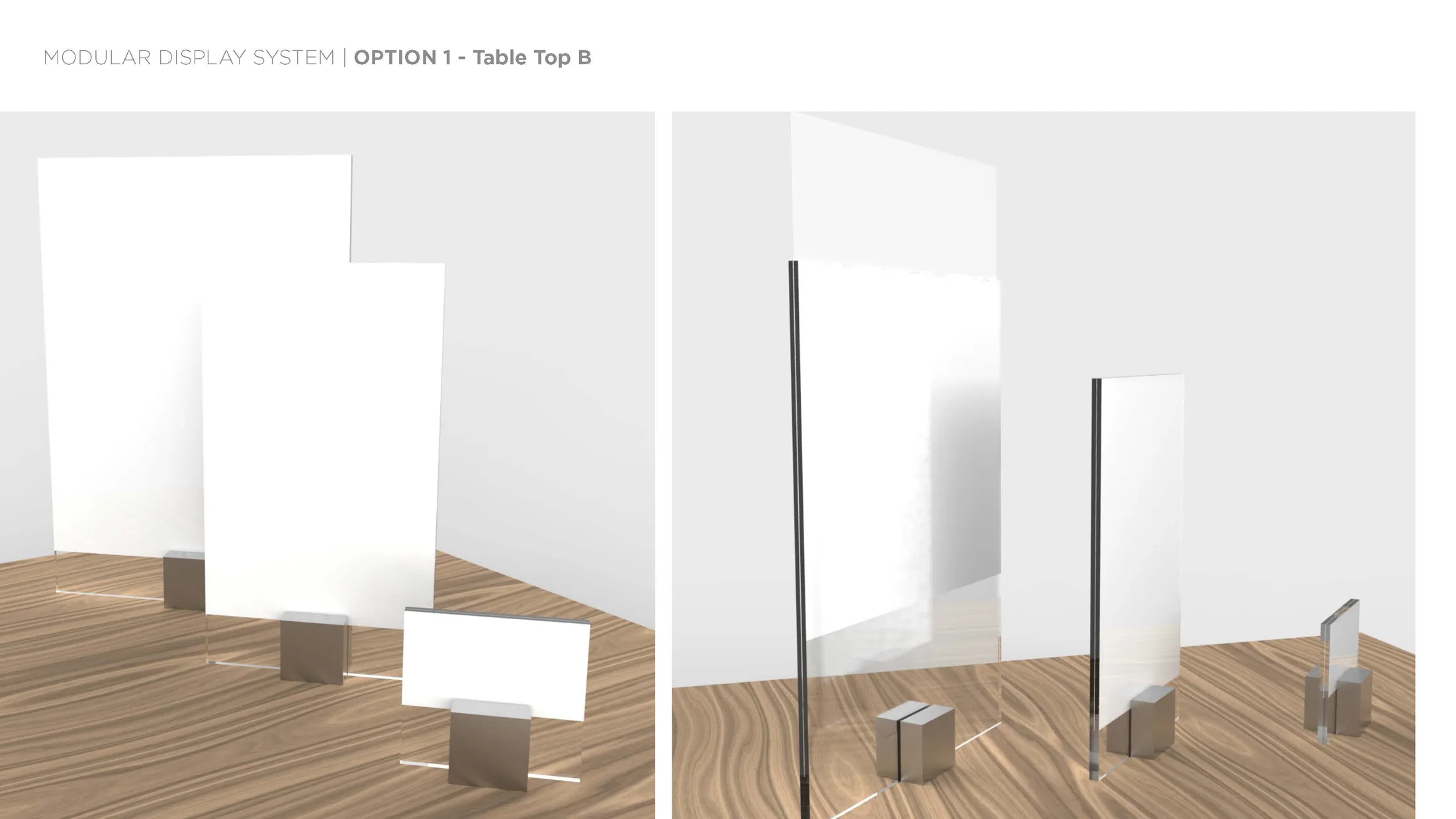
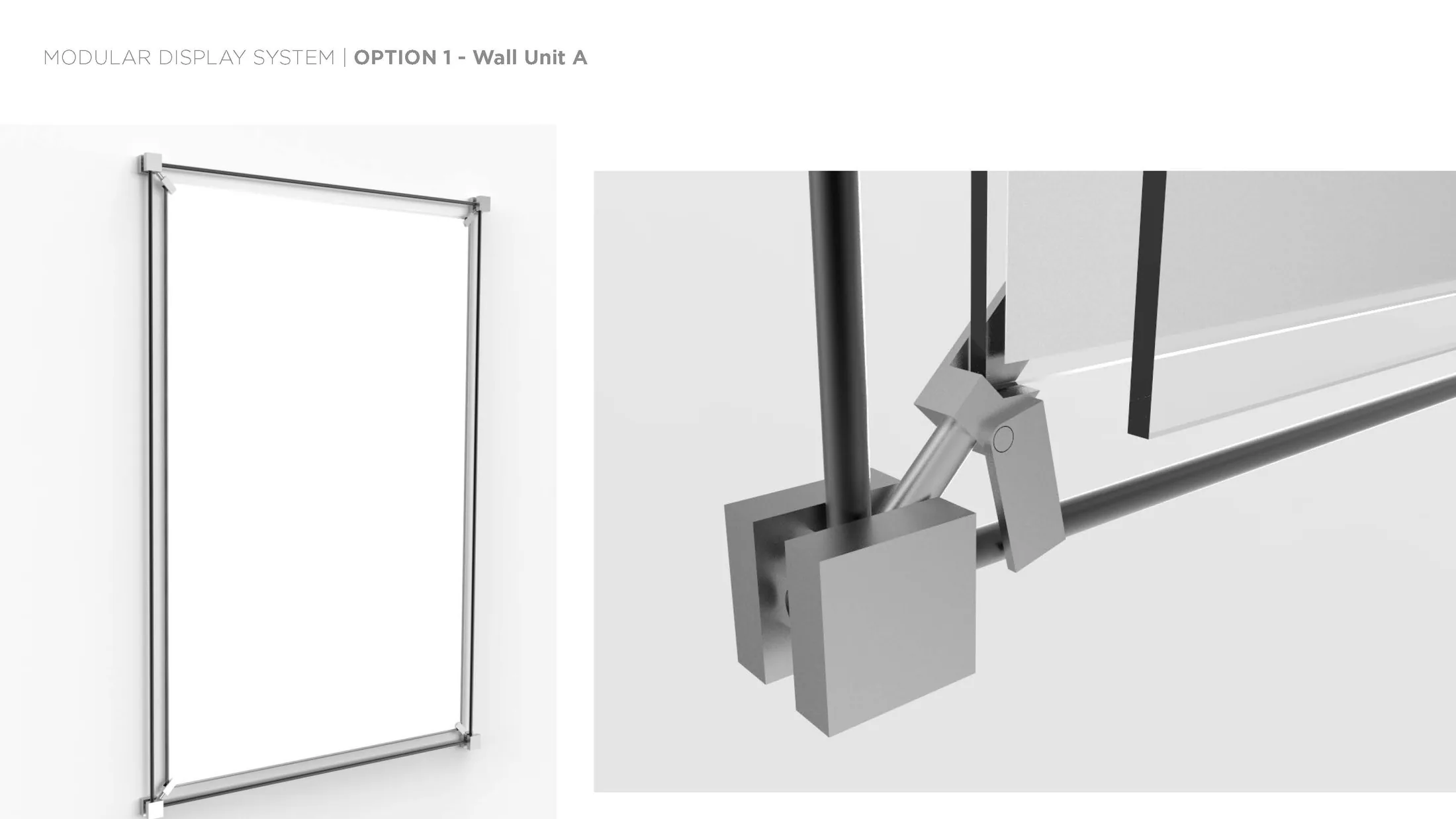
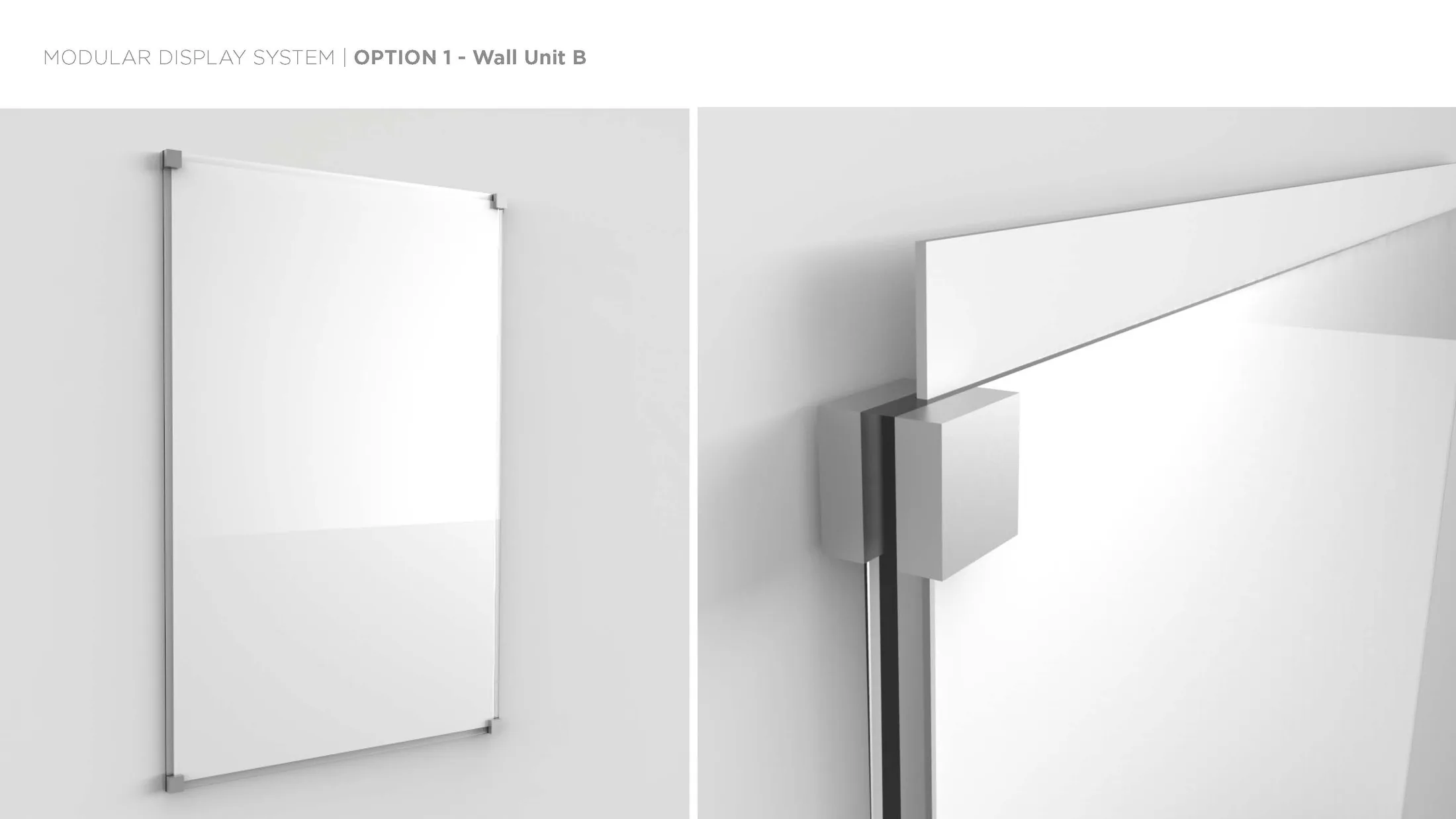
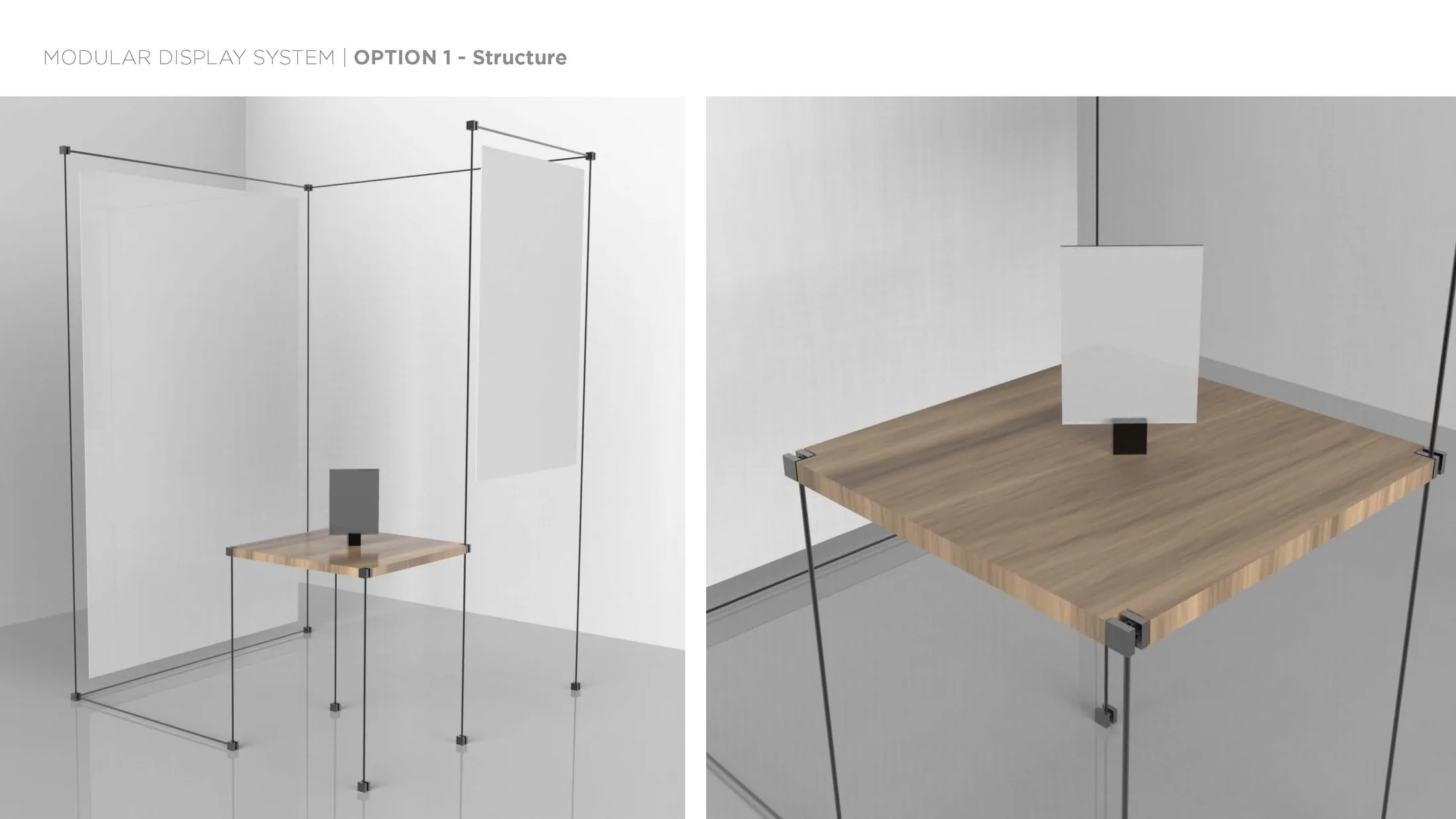
The first direction uses a repeatable cube-like connector. A small set of parts could produce a tabletop arrangement or grow into a wall-mounted, hanging, or freestanding display. The study tested how that single connection would read at different scales.
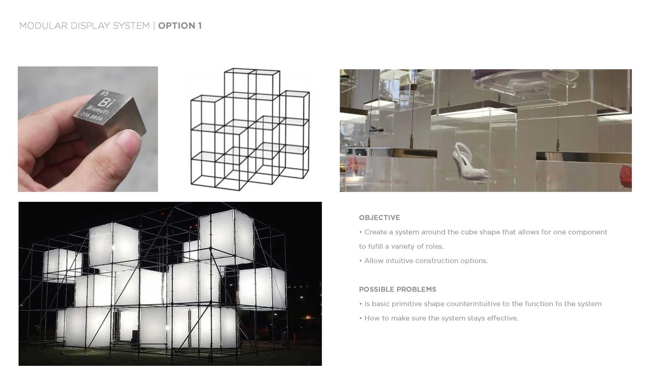
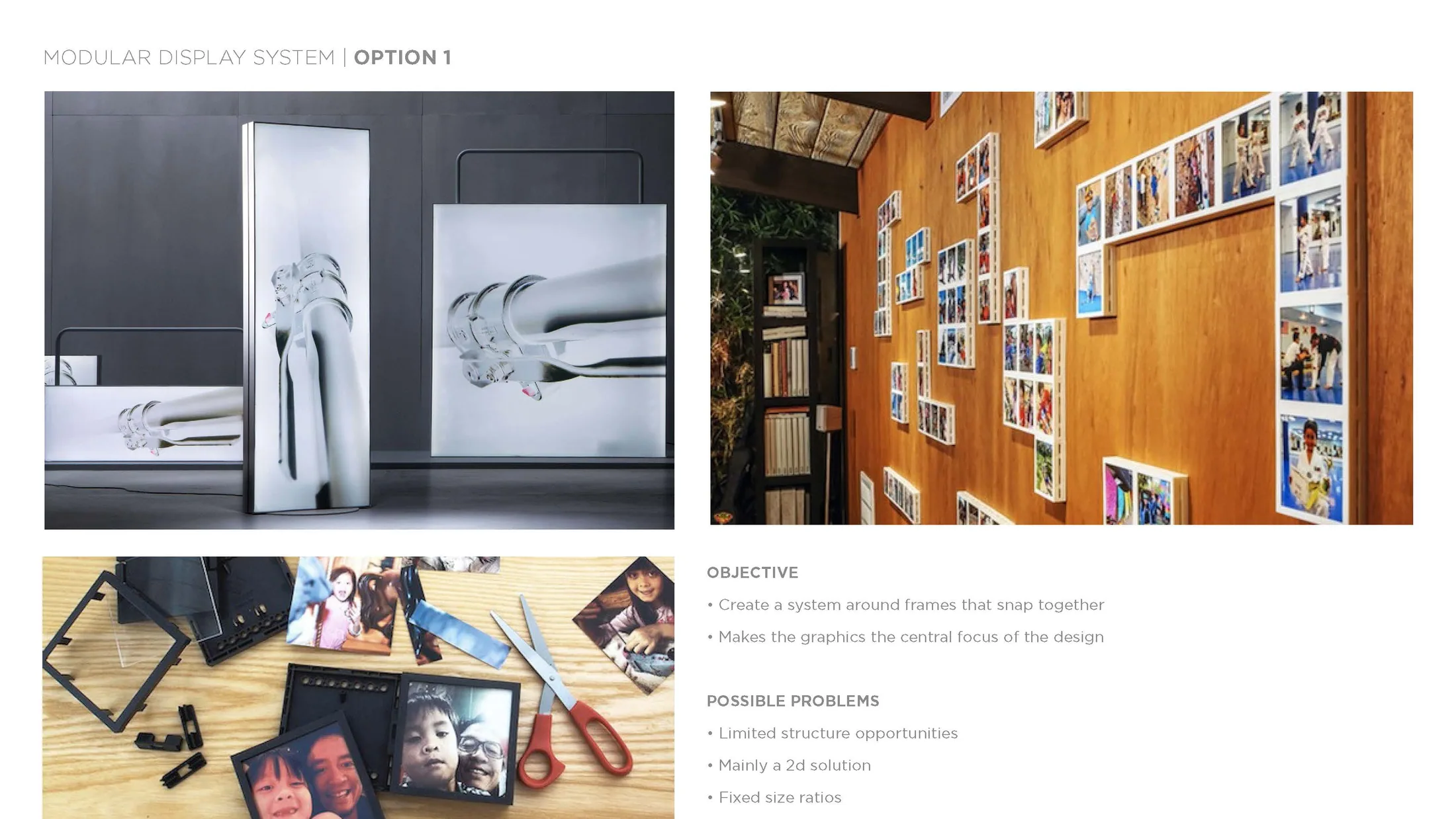
Reference for a repeatable node in the Structure VGS concept presentation
17Reference for a repeatable node
First structure sketches in the Structure VGS concept presentation
18First structure sketches
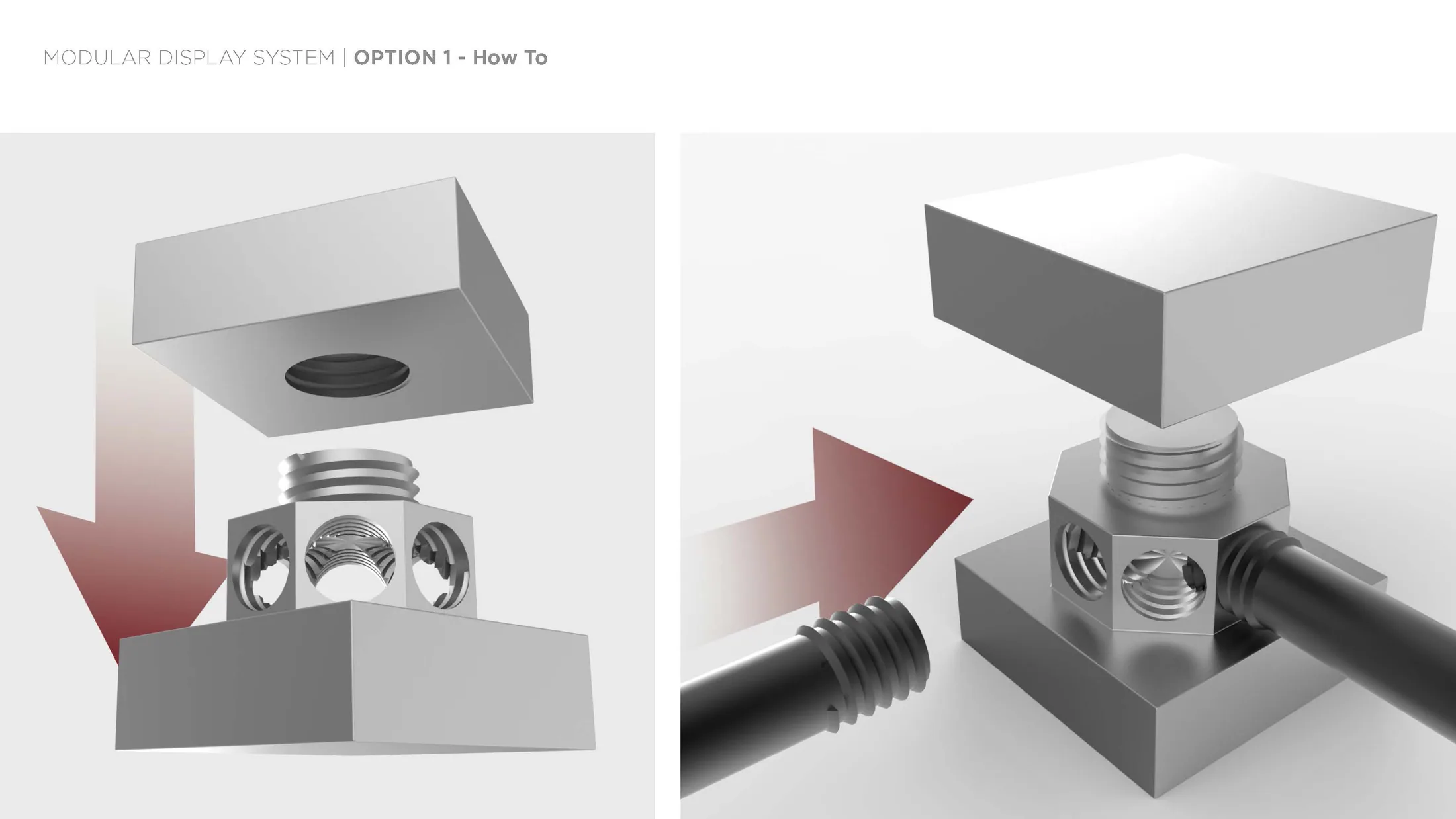
The central connection in the Structure VGS concept presentation
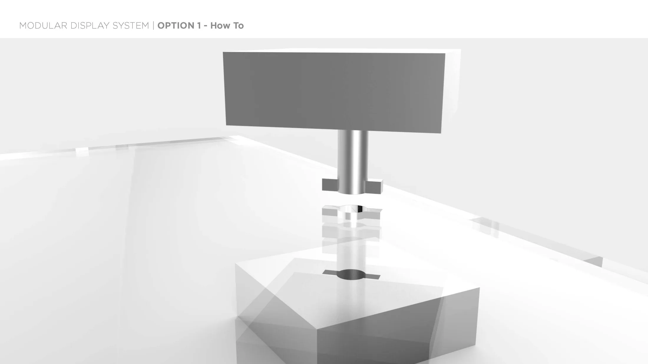
19The central connection
How the parts join in the Structure VGS concept presentation
20How the parts join
Color and component studies in the Structure VGS concept presentation
21Color and component studies
Variation in color and placement in the Structure VGS concept presentation
22Variation in color and placement
Tabletop configuration in the Structure VGS concept presentation
23Tabletop configuration
Wall configuration in the Structure VGS concept presentation
24Wall configuration
Hanging configuration in the Structure VGS concept presentation
25Hanging configuration
Freestanding configuration in the Structure VGS concept presentation
26Freestanding configuration
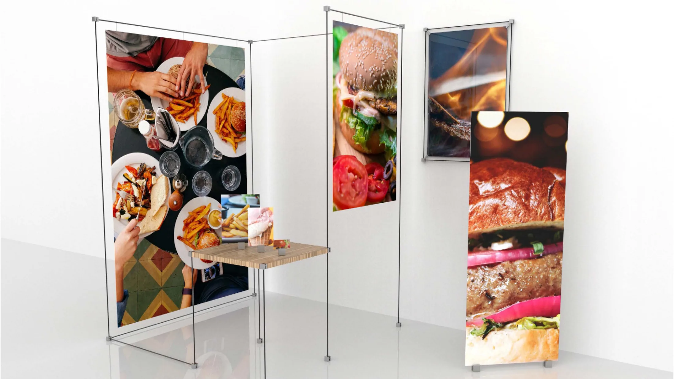
A larger modular arrangement in the Structure VGS concept presentation
27A larger modular arrangement
Display surfaces within the frame in the Structure VGS concept presentation
28Display surfaces within the frame
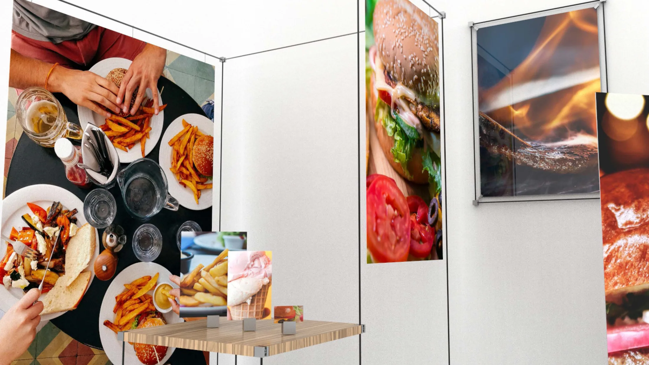
Merchandise application in the Structure VGS concept presentation
29Merchandise application
Retail setting study in the Structure VGS concept presentation
30Retail setting study
The cube system in use in the Structure VGS concept presentation
31The cube system in use
04

Option two

Connect tubes into a system

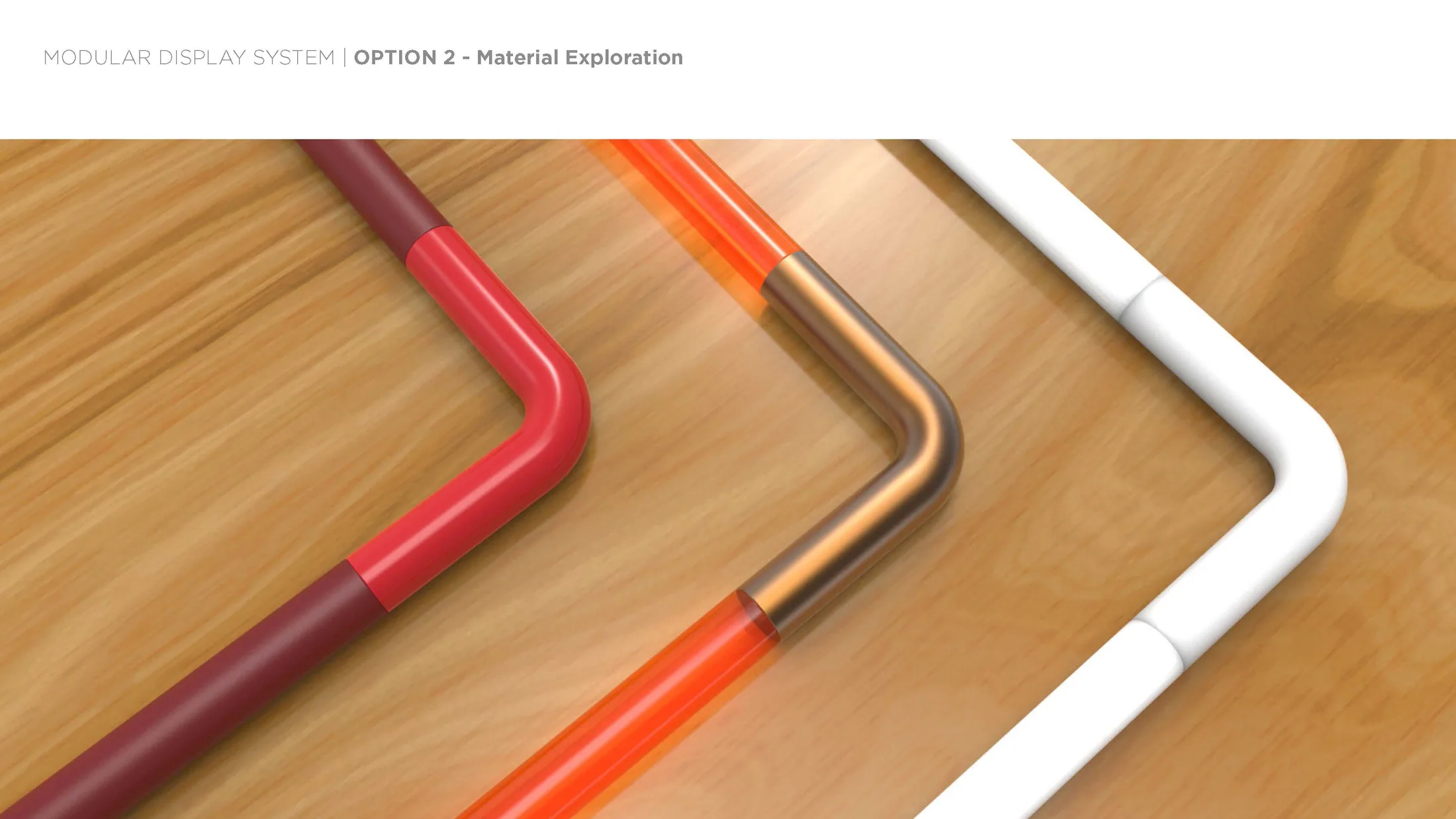
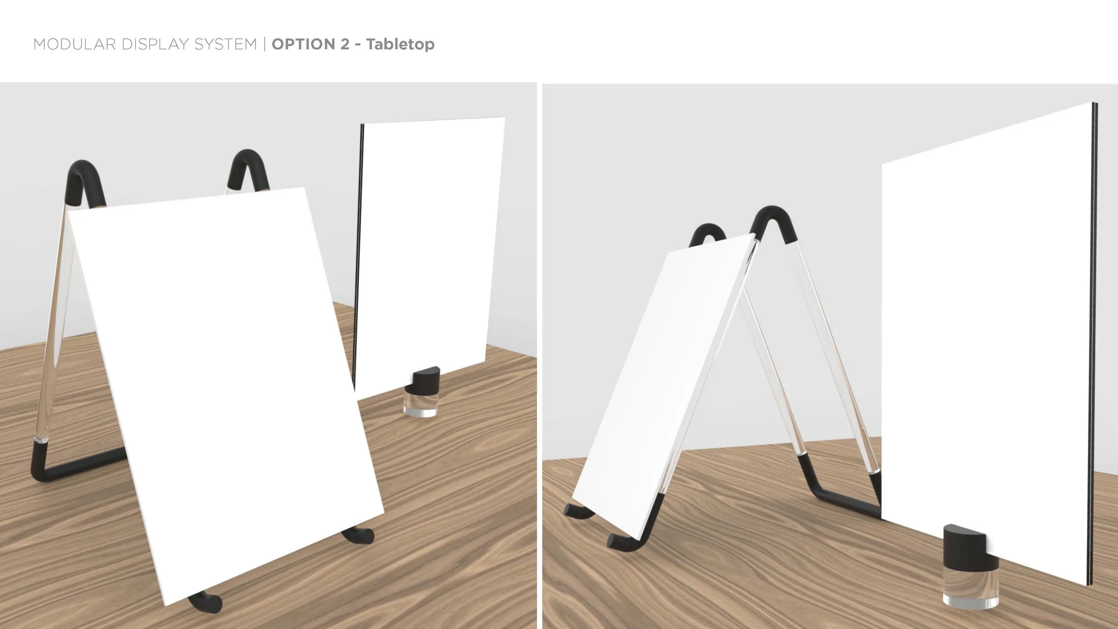
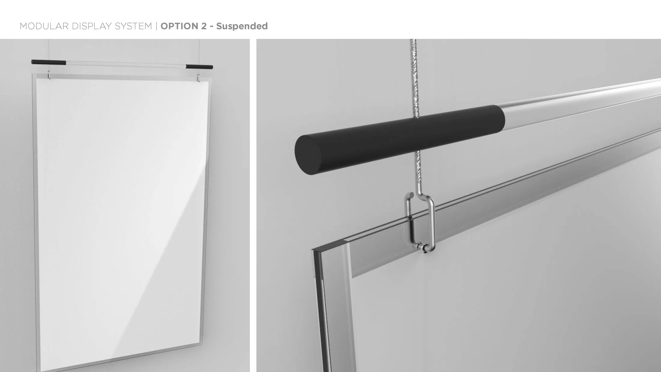
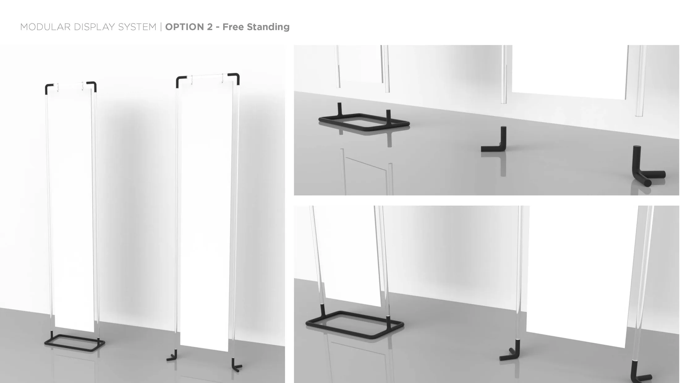
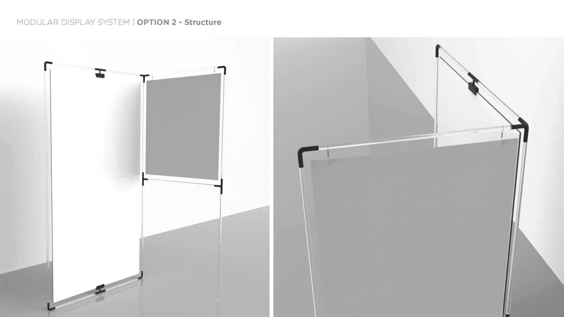
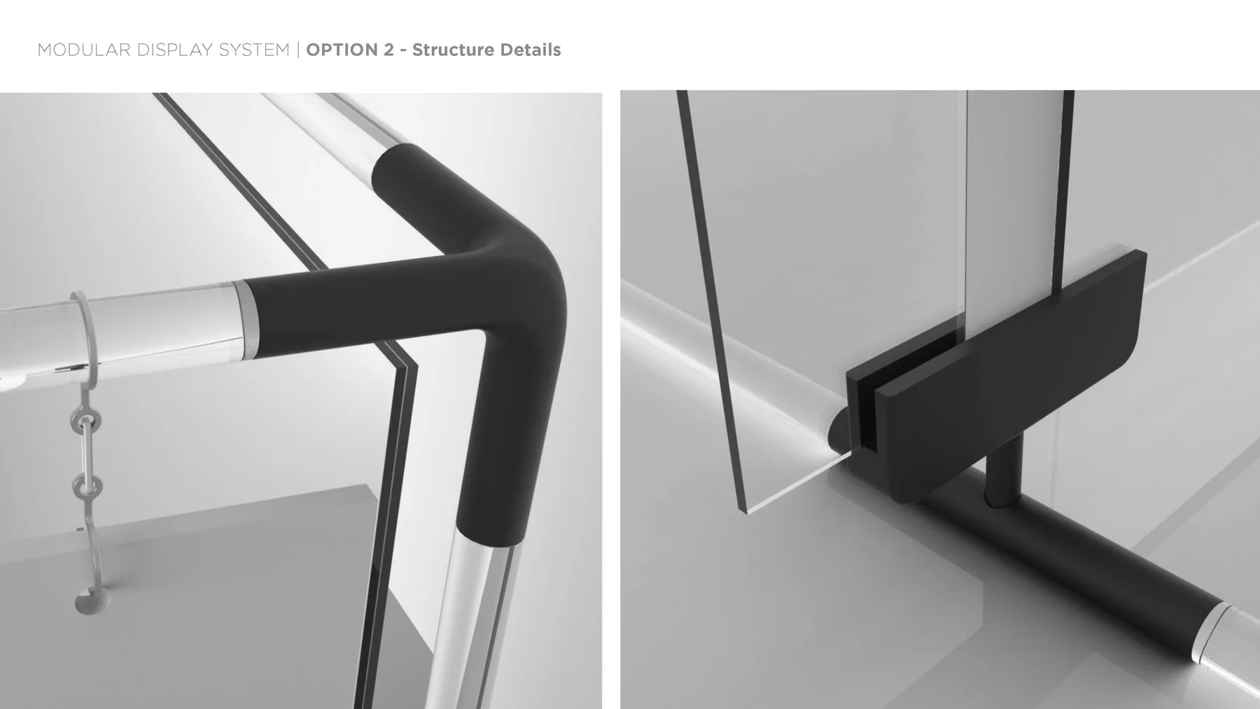
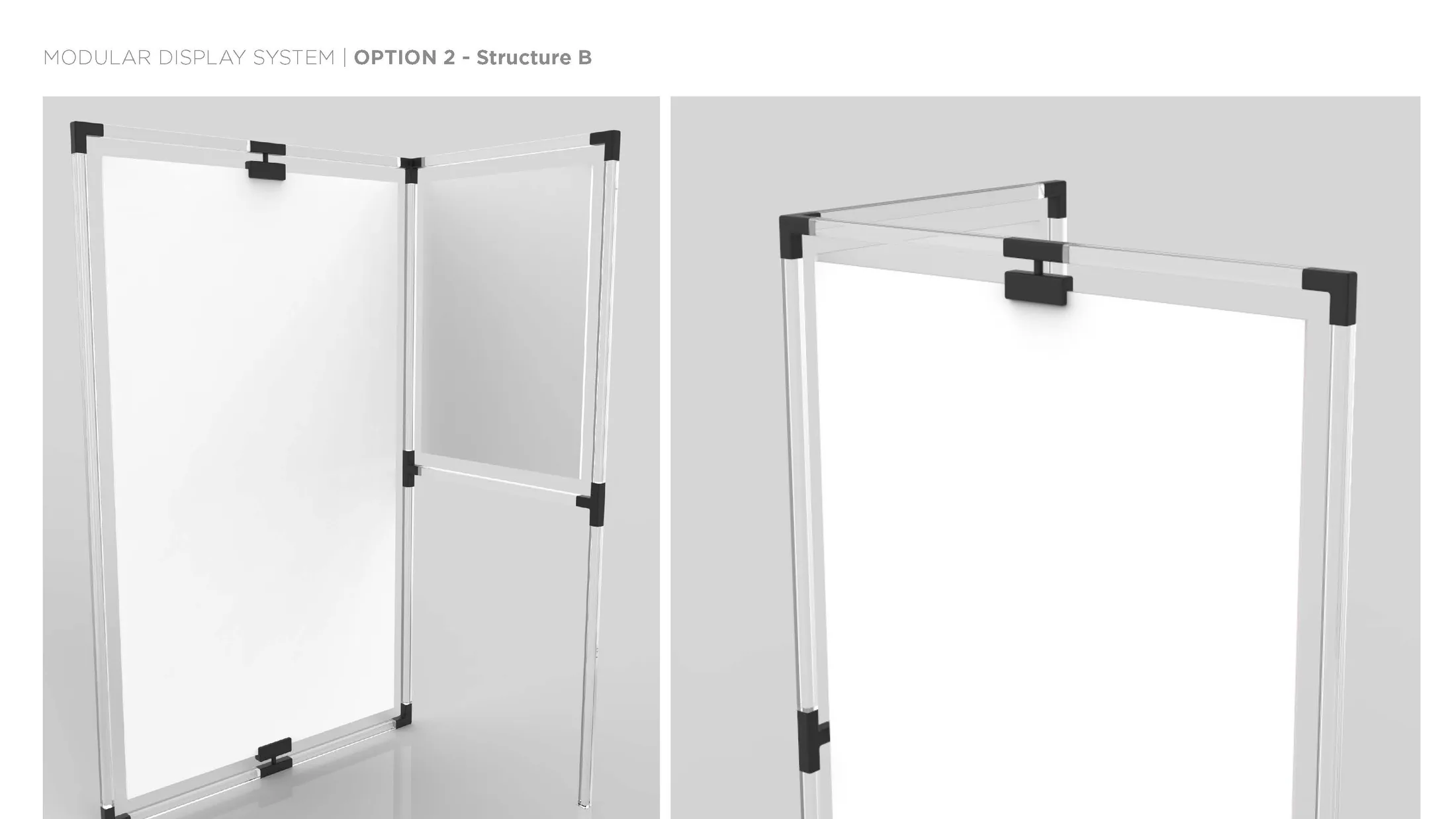
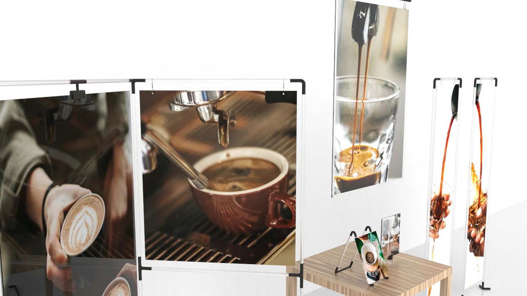
The second direction replaces the solid node with a lighter tube structure. I studied how its joints, surface treatments, and graphic panels could work together, then tested the same system across tabletop, hanging, and freestanding configurations.
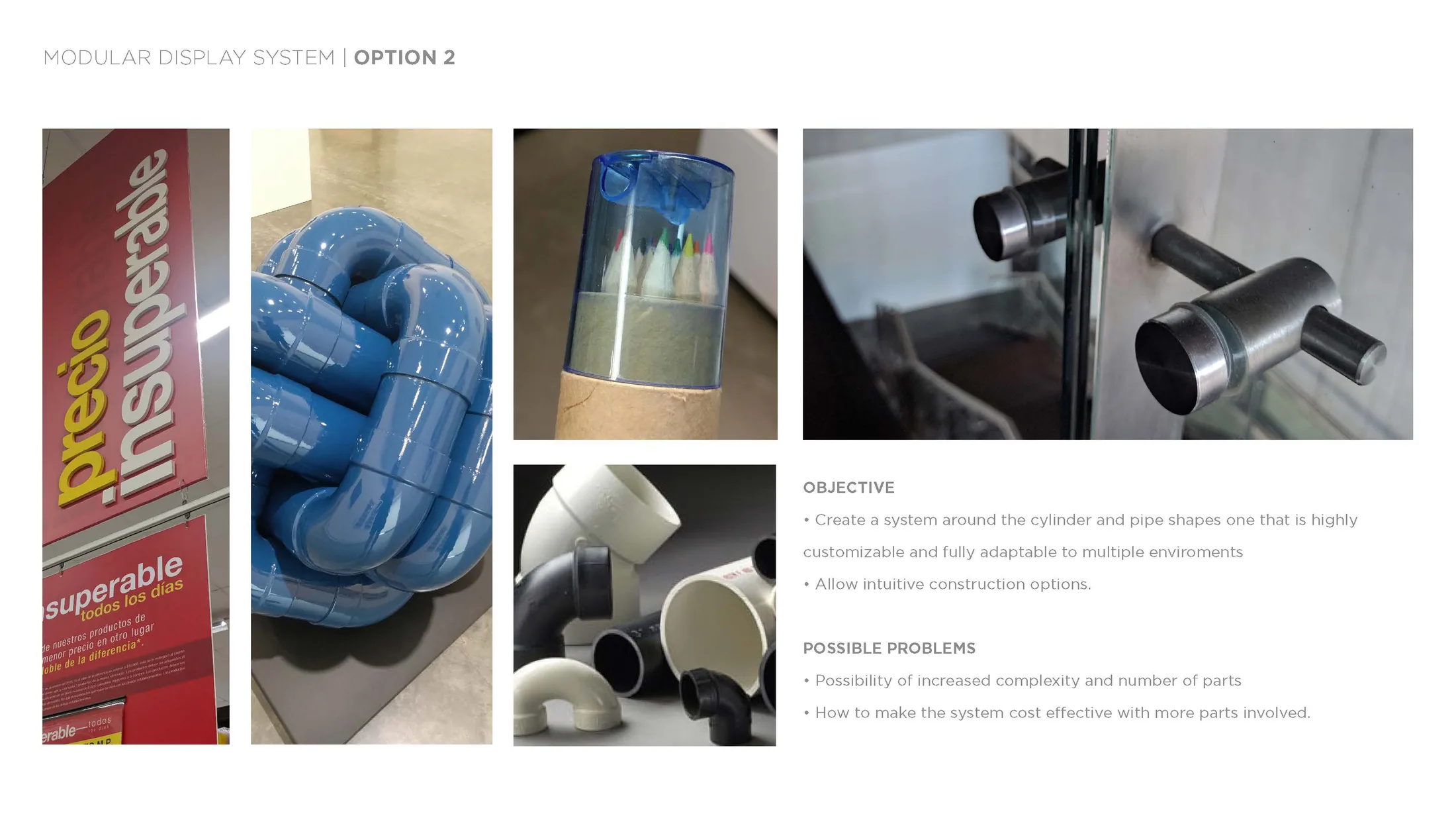
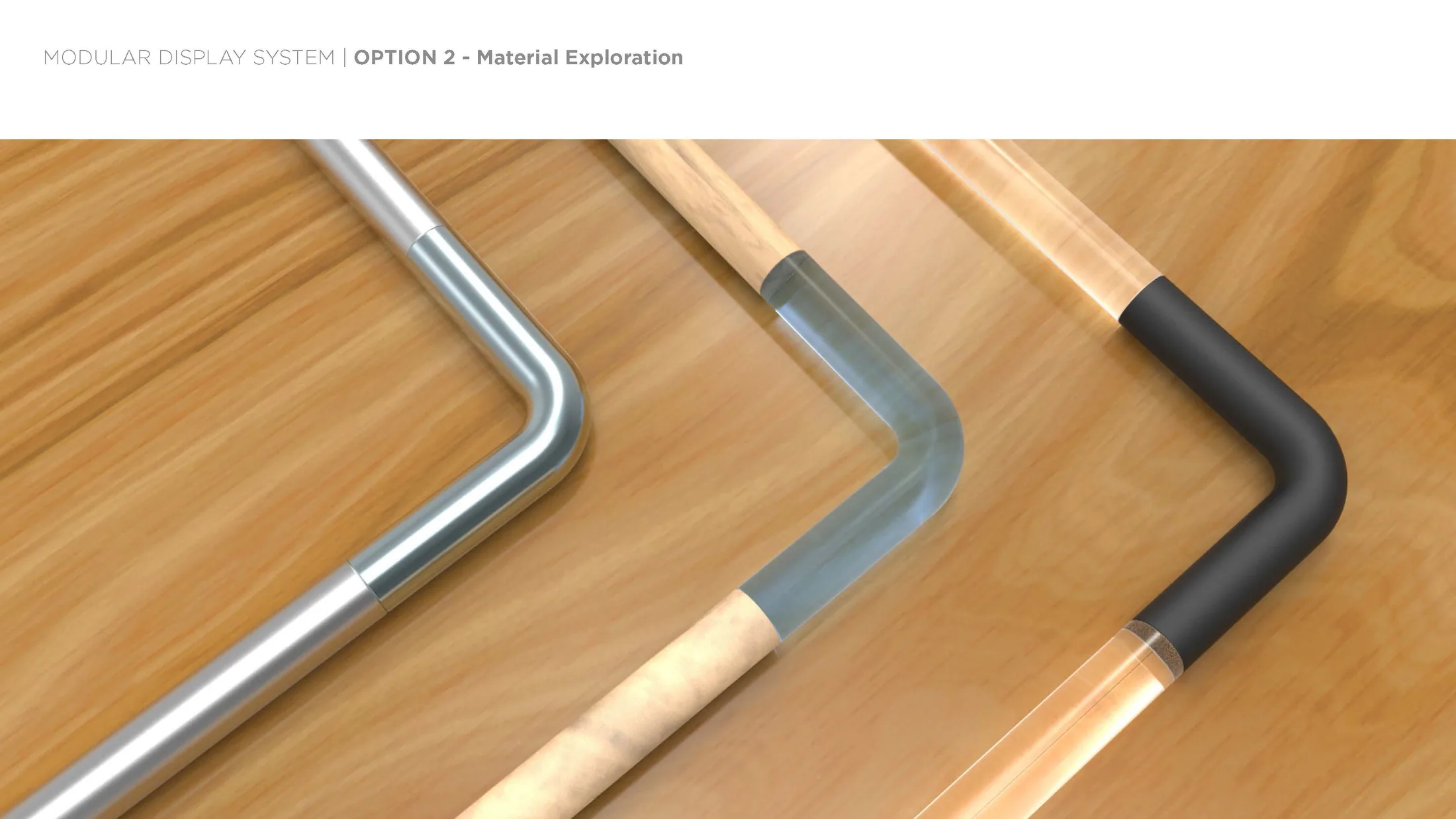
The tube system direction in the Structure VGS concept presentation
32The tube system direction
Material and color references in the Structure VGS concept presentation
34Material and color references
Initial tube studies in the Structure VGS concept presentation
35Initial tube studies
How the frame can change size in the Structure VGS concept presentation
36How the frame can change size
A tabletop arrangement in the Structure VGS concept presentation
37A tabletop arrangement
A hanging arrangement in the Structure VGS concept presentation
38A hanging arrangement
Open modular frame in the Structure VGS concept presentation
39Open modular frame
Connection and joint details in the Structure VGS concept presentation
40Connection and joint details
Freestanding frame study in the Structure VGS concept presentation
41Freestanding frame study
Graphic placement within the structure in the Structure VGS concept presentation
42Graphic placement within the structure
Retail display application in the Structure VGS concept presentation
44Retail display application
05

Option three

Explore a flexible support

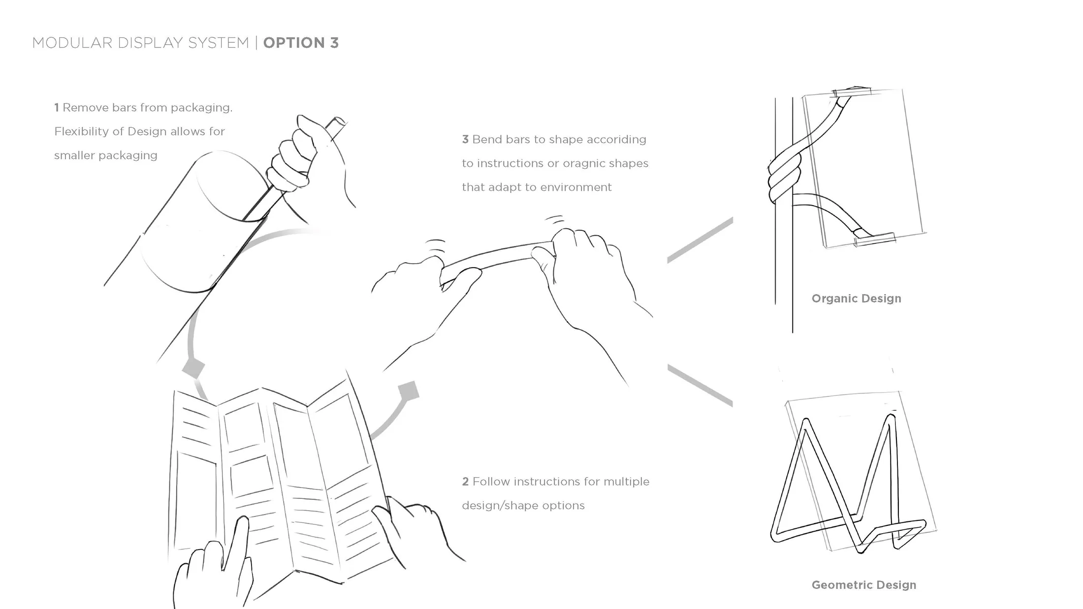
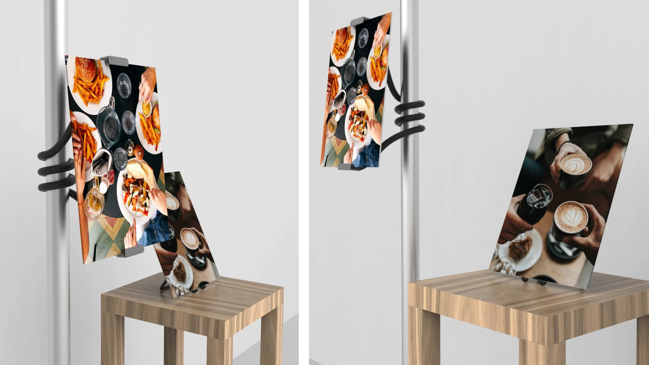
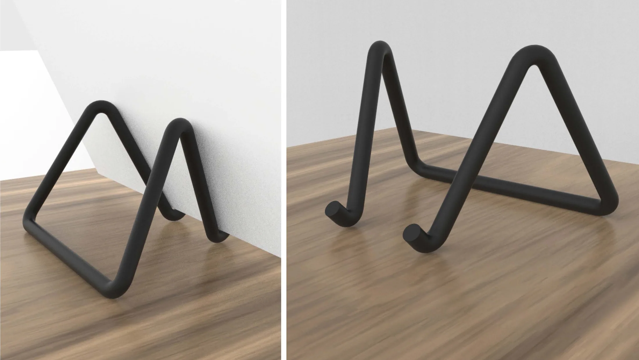
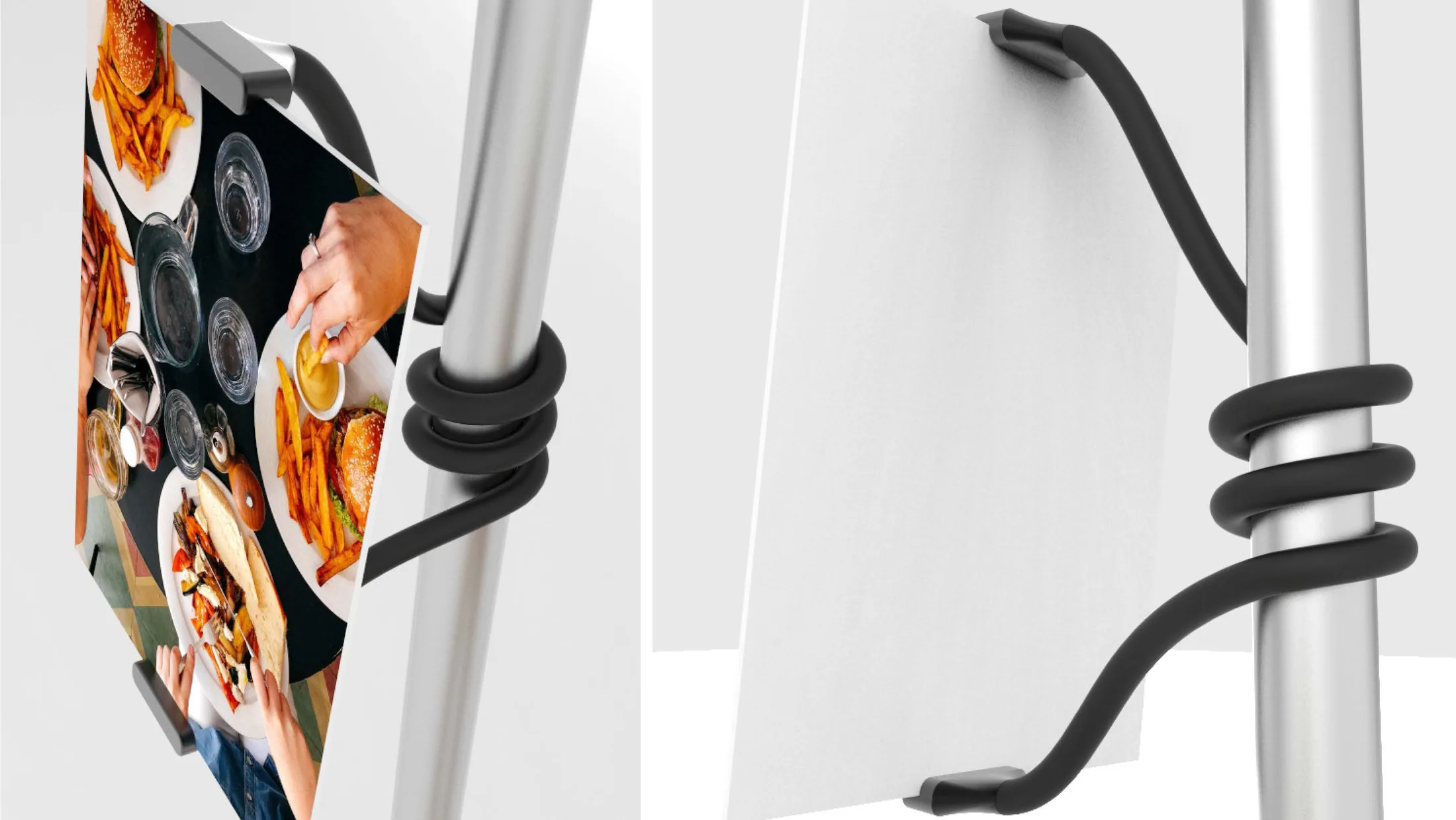
The third direction tests a softer, more flexible support. Rather than repeating rigid frames, it looks at how rods and a stable base might hold product or graphics while giving each configuration a different silhouette. The concept still needs engineering and durability testing.
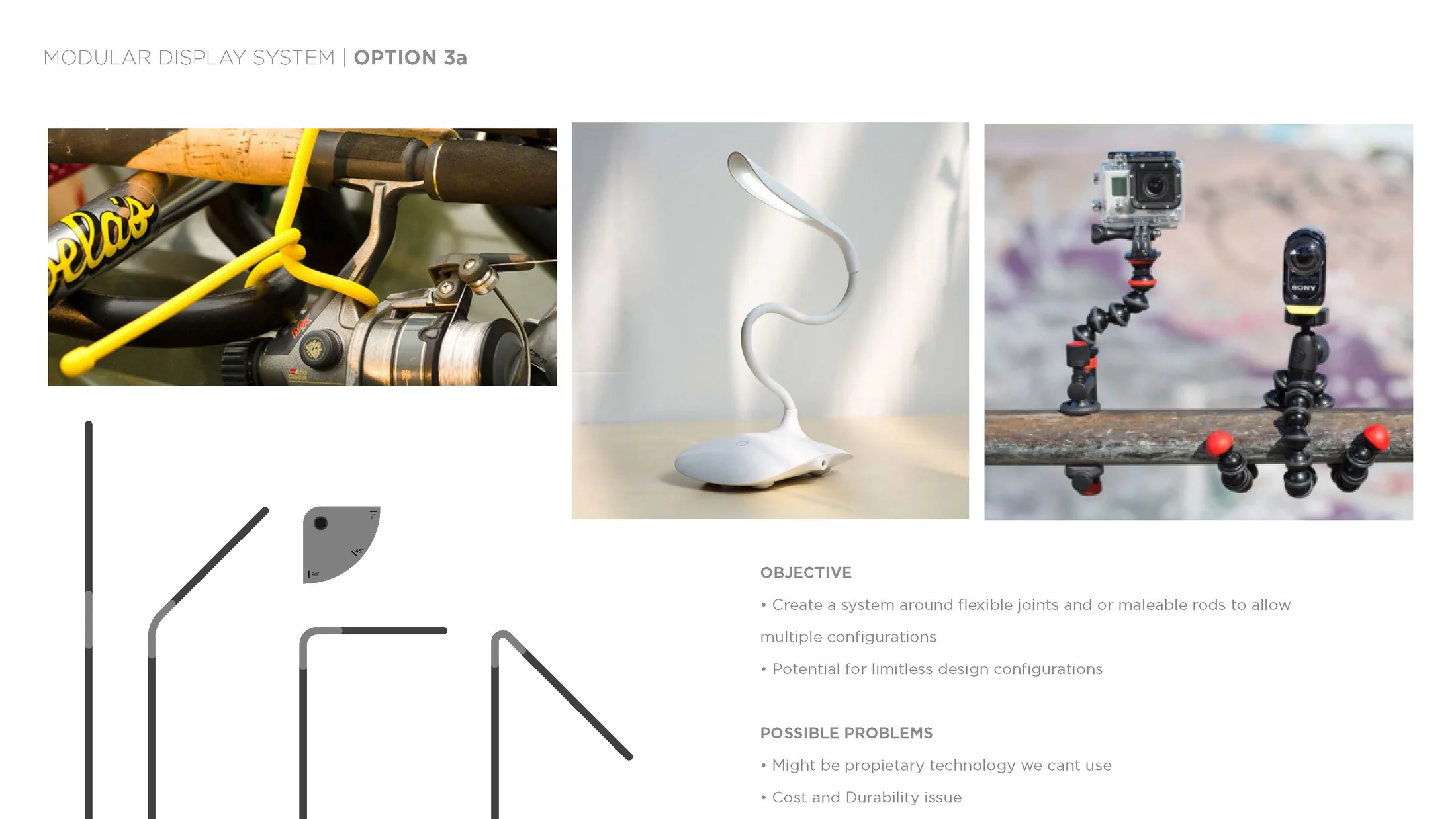
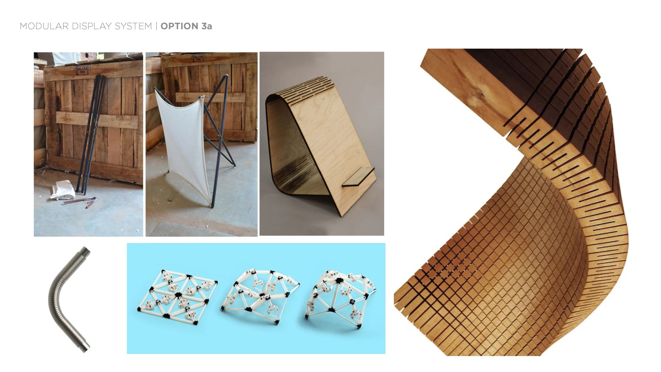
The flexible support direction in the Structure VGS concept presentation
45The flexible support direction
Early form sketches in the Structure VGS concept presentation
46Early form sketches
Flexible rod arrangement in the Structure VGS concept presentation
47Flexible rod arrangement
Rendered concept in the Structure VGS concept presentation
48Rendered concept
Base and support study in the Structure VGS concept presentation
49Base and support study
Component detail in the Structure VGS concept presentation
50Component detail
06

Next steps

Where the study stopped

The presentation ends in refinement. Modeling, engineering, and production appear as proposed next steps, not completed outcomes. The work established three credible directions and made the decisions still needed for production easier to see.
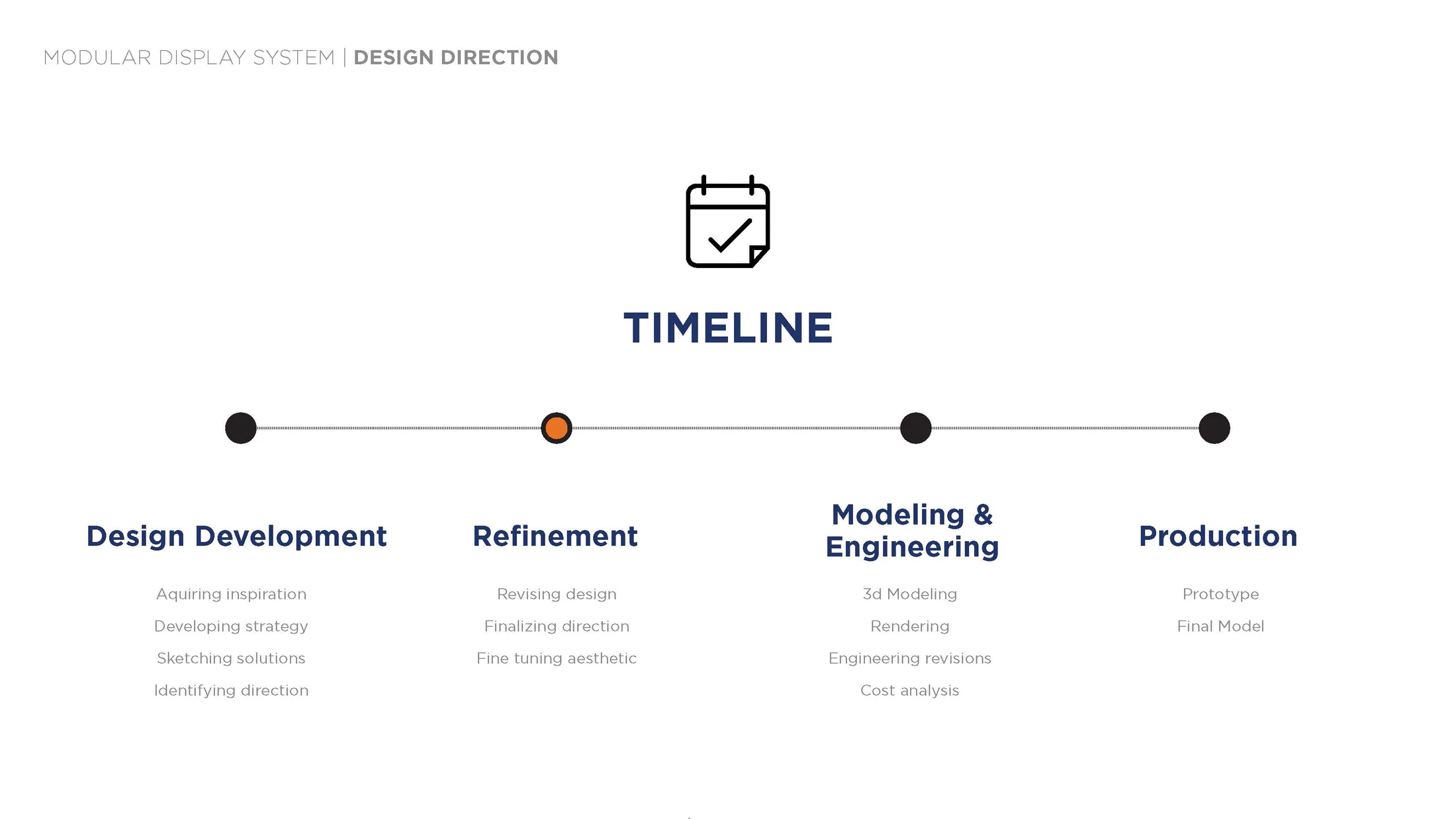
Project stages and proposed next steps in the Structure VGS concept presentation
51Project stages and proposed next steps

The point was not one fixed fixture. It was a set of choices about how a display could adapt without losing its identity.

Start a conversation

What do you
have in mind?

A few details is enough. I’ll reply by email.

What can I help with?

Choose any that fit. It’s OK if you’re still figuring it out.

Straight to Brian.
No mailing lists.